


14
3.1 Function Specifications
■ Function Specifications
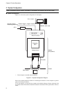
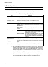
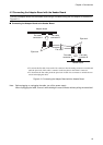
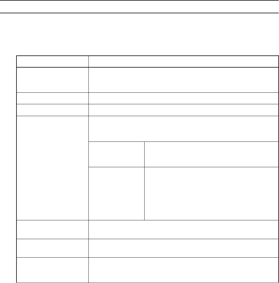
Table 3.1-1 lists the major function specifications of the adapter. Figure 3.1-1 is a block diagram of
external-memory emulation.
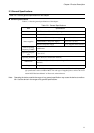
Table 3.1-1 Adapter Function Specifications
*1 : The evaluation MCU must support the external-memory emulation feature. The total amount
of memory available depends on the memory capacity of the memory board, its memory ca-
pacity select switch, and the settings of the evaluation MCU. Refer to the "Evaluation MCU
Hardware Manual" or Please ask, when unknown before use. For details, see Section 5.4 "Ex-
ternal-Memory Emulation Settings."
Note also that this function is added to the external bus of the evaluation MCU. Before using
the function, read Chapter 6 "Cautions" carefully.
*2 : This function assumes that the evaluation MCU supports the power-on debug feature. Refer to
the "Evaluation MCU Hardware Manual" or Please ask, when unknown before use.
Table 3.1-1 lists the major function specifications of the adapter.
Item Description
Adapter Function
Serving as the adapter used in combination with the DSU-FR emulator and header
to provide connection between the emulator and evaluation MCU and betweenthe
evaluation MCU and user system.
External trace memory Supporting the external trace function. Trace length of 64 K frames
Internal ROM emulation
Supporting the internal ROM emulation memory function. 1 megabytes max. *
1
External-memory emulation
Supporting the external-memory emulation *
2
function. Capable of setting RAM/
ROM. This function is implemented by mounting an optional memory board on
the adapter board.
Memory capacity
switching
Capable of selecting the capacity of the memory board
from among seven steps between 2M words and 32K
words(1word=16bits).
Memory connection
Capable of disconnecting address lines disabled by the
memory capacity switching function from buffers and us-
ing them as user resources instead.
Also capable of reducing the load applied during use of
such address lines as user resources by disconnecting
them even when the external-memoryemulation function
is not used.
Power-on debugging
Supporting the power-on debug function *
3
which runs a program immediately af-
ter the power-on sequence of the evaluation MCU.
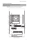
Jumper plugs
The jumper plugs on the adapter board can be used to make various settings of the
adapter.
Clock input IC sockets
The IC sockets for oscillator on the adapter board supply clock signals from the
adapter to the main clock (X0/X1) and subclock (X0A/X1A) pins of the evalua-
tion MCU.
Chapter 3 Functions