


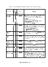
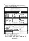
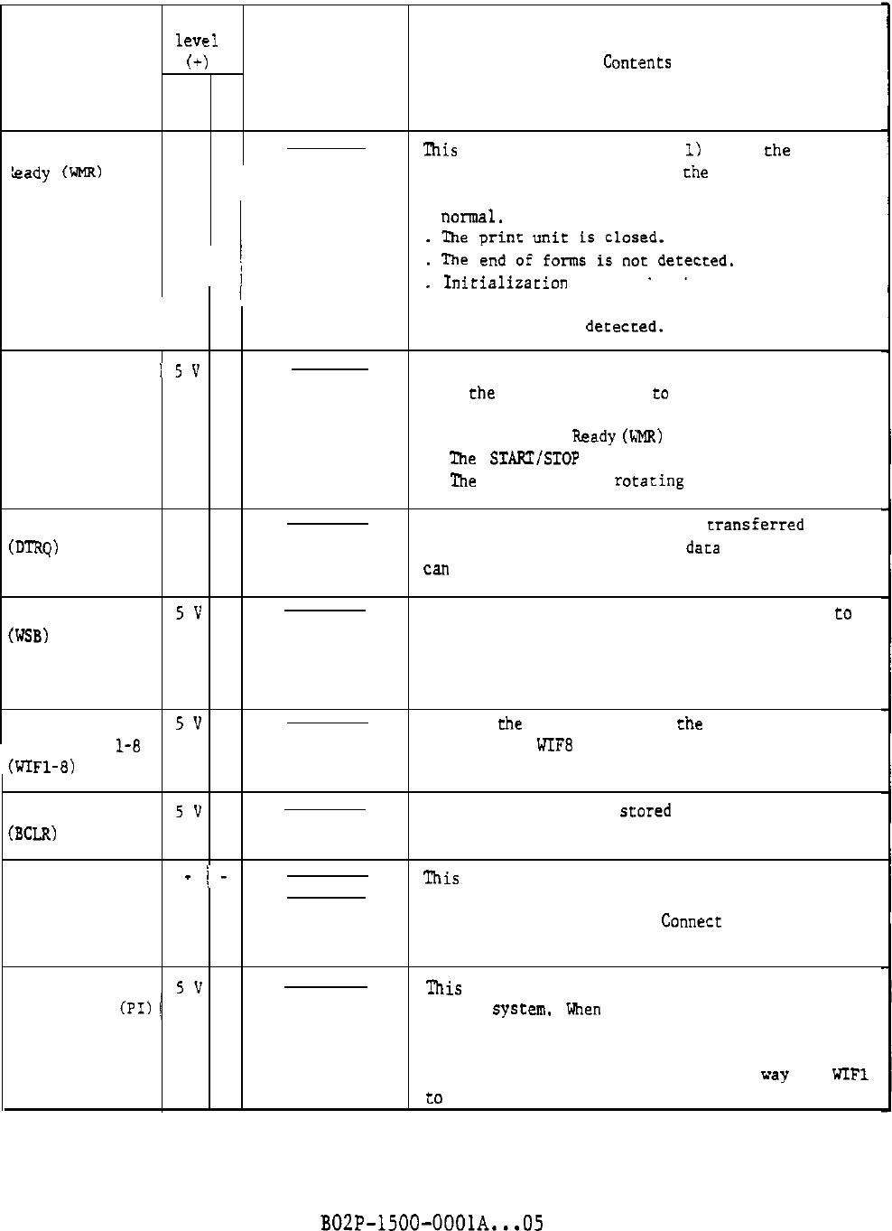
Table 4.1 DPC-compatible interface signal lines (Positive logic)
Signal
level
Signal name
(+)
Direction
COiltfSlltS
1 0
System-Printer
kite Machine
5v 0
This signal is high (logical
1)
when the following
Leady
mire
conditions are satisfied for
the
printer:
1 j
1
. Power has come on and all voltage levels are
nollna1.
i
EE
H~~"b,"~~:'i:'~~:",e,.,,ed.
Initlallzatxon process has been completed.
. The hammer drive system is normal.
. An error is nor dececced.
Online
'5V
0
This signal enables information to be transmitted
with the system connected
to
the printer and goes
high when the following conditions are satisfied:
. Write machine
beady
(FMR)
is 1.
. The START/STOP switch is pressed.
. The print band is rotaxing normally.
Data Request
5v 0
A synchronizing signal for data transferred from
CDTRQ,
the system, and is high when daEa from the system
can be accepted.
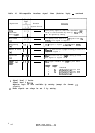
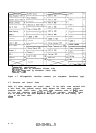
Write Strobe
5v
0
This is a strobe signal for Write Information
to
(WSB)
the printer. The printer resets its Data Request
signal when the leading edge of this strobe signal
is received.
Write
5v
0
This is
the
input data from the system. (For ASCII
Information
l-8
7-bit codes, WIFE can be ignored by setting.)
(WIFl-8)
Buffer Clear
5v
0
The data for one line scored in the buffer of the
(BCLR)
printer is cleared by this signal.
connect 1
-
i-
This signal is used for confirming the connection
Connect 2 of the interface connector.
When the interface
connector is connected, the Connecr 1 and Connect 2
lines are connected.
Paper
5v
0
Instruction
(PI)
/
'Ibis
signal is high when forms control is performed
by the sysrem. When this signal is logical 1, the
input data on the WIF lines is stored in the FCB.
This signal is checked 'by the printer at the timing
of the Write Strobe signal in the same way as WIFl
to
WIFE. For derails, see Section 4.4.2.
BOZP-1500-OOOlA...05 4-3