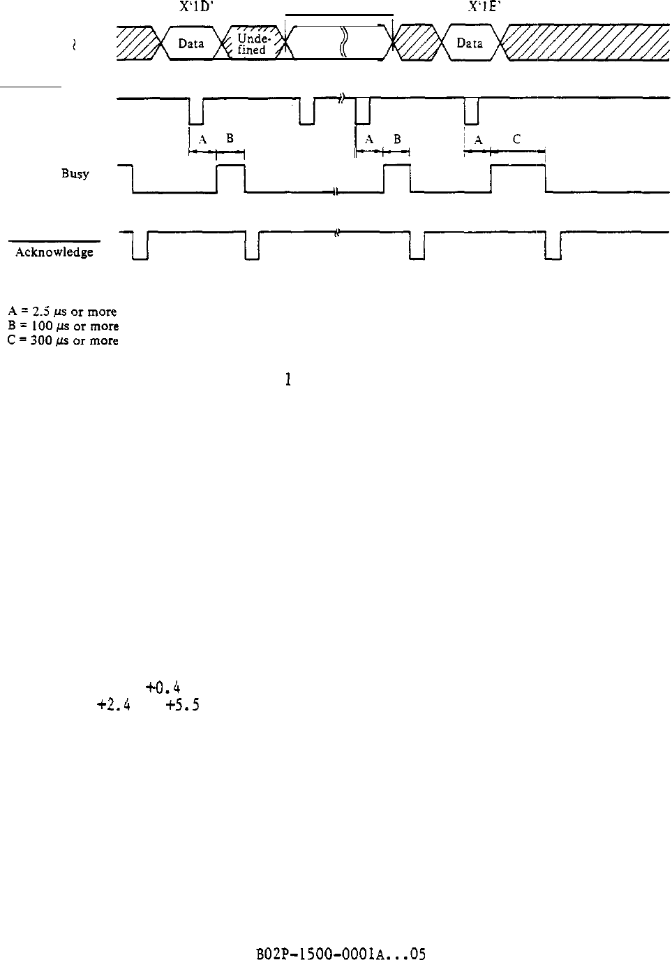
Start code
X‘ID'
VFU data
Stop code
I I
X'IE'
Data Bit I
l
Data Bit 8
Data Strobe
Note:
The Busy signal is st to
1
ech time an FCB data byte is received
during a sequence between the start and stop codes.
Figure 5.7 FCB data receive timing chart
5.2.2 Physical specifications of interface signals
The physical specifications of Centronics-interface signals consist of
electrical specifications, interface cable specifications, and connector pin
assignment specifications.
(1) Electrical specifications
Signal levels must be within the following ranges:
Low 0.0 to +0.4 v
High
+2.4
to
+5.5
V
Note:
The signal level above are at the interface connector.
Incorrect signals may be issued at power-on and power-off.
The interface signal driver and receiver must be the same as those shown
in Figure 5.8.
5
-8
BOZP-1500-OOOlA...05


