


6.2
,Interface
Signals
This section explains the interface signal functions and physical
specifications.
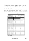
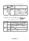
6.2.1 Interface signal lines
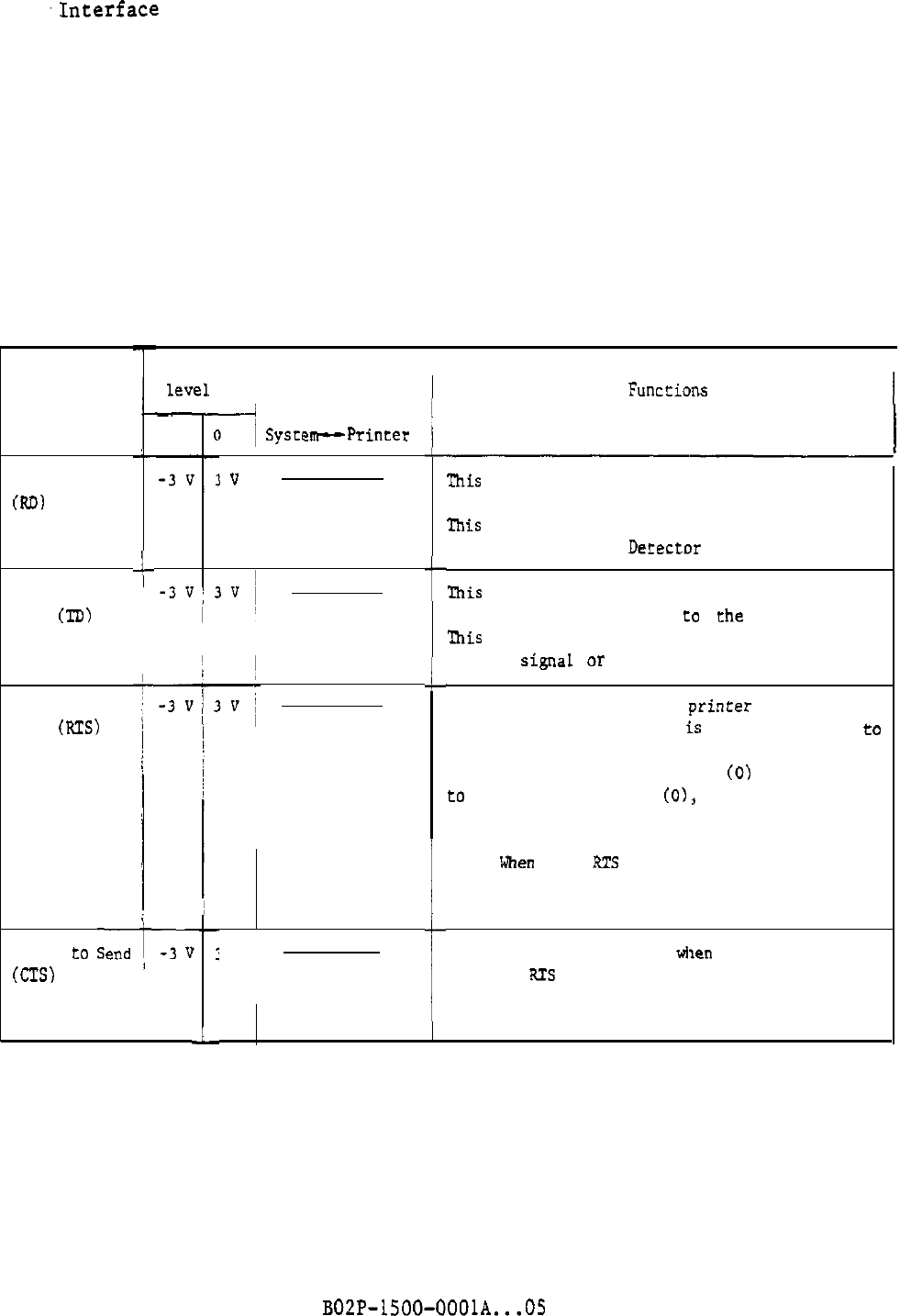
The RS-232-C interface uses
negative
logic when the positive voltage is logical
0 and the negative voltage is logical 1. Table 6.1 lists the RS-232-C
interface signal lines and their functions.
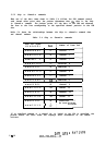
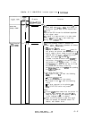
Table 6.1 RS-232-C interface signal lines
Signal name
Received Data
@.D)
i
Transmitted
Data
(TD)
Request to
Send
(RTS)
Signal
I
I
level
I
Direction
1
Funceions
I
-
1
I
Clear
to
Sendt-3
U
(CTS)
i
L
7
SystepPrinter
I
v
IV /
t
I
i
I
L
This signal line receives serial data from the
host.
This signal line must be 1 (marking) when the
Received Line Signal Detector line is logical 1.
mis
signal line transmits codes XON and XOFF,
and reports printer status
to
the host.
'Ihis
signal line is 1 (marking) when the Request
to Send signal or Clear to Send signal is 1.
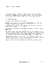
When this signal is 0, the
printer
is requesting
the host to send data or
is
transmitting data to
the host.
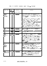
After this signal is turned on
(0)
and the Clear
to
Send signal goes on
CO):,
the printer begins
transmitting data. For operation details, see
Table 7.2.
Note: When the RTS line protocol is used, this
signal does not operate as described
above.
For
details, see Section 4.4.
This signal is turned on
wl~en
the host confirms
that the RTS is 0 and data from the printer can
be received. For operation details, see Table
7.2.
6-4
BOZP-1500-OOOlA...OS