Pin
!
NO.
1
25
24---------------
_---_
,s ,J
Pin
Signal name
No.
Signal
rime
Frame Ground
14 (Reserved~
8
I
1
Received Line
21
I
1
(Reserved)
Signal Detector
I
9
(Reserved)
22
10 1
(Reserved)
23
Ring Indicator
(Reserve'd)
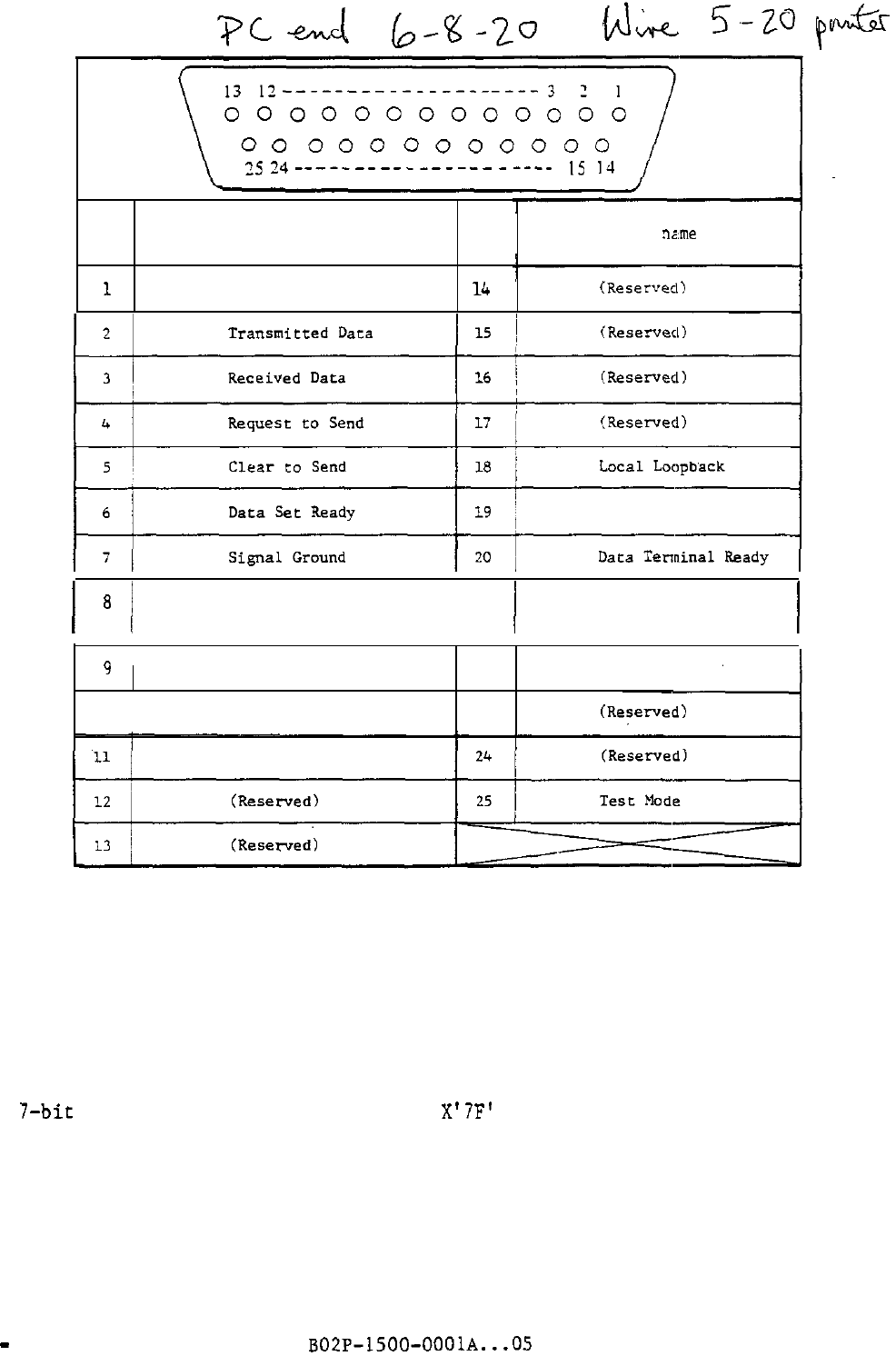
Figure 6.10 RS-232-C interface connector pin assignment
6.3 Character and Control Codes
Table 6.4 shows character and control codes. In the table, areas enclosed with
a bold-faced line indicate control codes, whereas the other areas indicate
character codes (ASCII codes). The table shows character codes of S-bit mode.
In
‘/-bit
mode, character codes X'OO' to
X'7F'
are available. Character codes
with an asterisk in the table vary depending on the print band for each
country,
as shown in
the lower
table.
6
-
14


