


xii C141-E035-03EN
FIGURES
page
1.1 MAA31xxSC outer view................................................................................................ 1-5
1.2 MAA31xxSP outer view ................................................................................................ 1-6
1.3 MAB30xxSC outer view ................................................................................................ 1-6
1.4 MAB30xxSP outer view................................................................................................. 1-7
1.5 MAC30xxSC outer view ................................................................................................ 1-7
1.6 MAC30xxSP outer view................................................................................................. 1-7
1.7 Disk/head configuration ................................................................................................. 1-8
1.8 System configuration...................................................................................................... 1-10
3.1 Cylinder configuration.................................................................................................... 3-2
3.2 Spare area in cylinders.................................................................................................... 3-5
3.3 Alternate cylinder ........................................................................................................... 3-5
3.4 Track format ................................................................................................................... 3-6
3.5 Track skew/cylinder skew .............................................................................................. 3-7
3.6 Sector format .................................................................................................................. 3-8
3.7 Alternate block allocation by FORMAT UNIT command ............................................. 3-14
3.8 Alternate block allocation by REASSIGN BLOCKS command..................................... 3-15
4.1 External dimensions (MAA31xxSC).............................................................................. 4-2
4.2 External dimensions (MAA31xxSP) .............................................................................. 4-3
4.3 External dimensions (MAB30xxSC, MAC30xxSC) ...................................................... 4-4
4.4 External dimensions (MAB30xxSP, MAC30xxSP)....................................................... 4-5
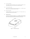
4.5 IDD orientation............................................................................................................... 4-6
4.6 Mounting frame structure ............................................................................................... 4-7
4.7 Limitation of side-mounting........................................................................................... 4-7
4.8 Surface temperature measurement points (MAA31xxxx/MAB30xxxx/MAC30xxxx) .. 4-8
4.9 Service clearance area..................................................................................................... 4-9
4.10 Air pressure adjustment hole .......................................................................................... 4-10
4.11 Current waveform (+12 VDC)........................................................................................ 4-11
4.12 Power on/off sequence (1).............................................................................................. 4-11
4.13 Power on/off sequence (2).............................................................................................. 4-12
4.14 Power on/off sequence (3).............................................................................................. 4-12
4.15 AC noise filter (recommended) ...................................................................................... 4-13
4.16 Connectors and terminals location (single-ended 16-bit SCSI) ...................................... 4-14