


C141-E035-02EN4 - 6
4.1.2 Mounting
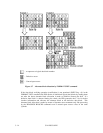
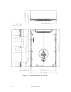
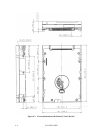
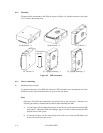
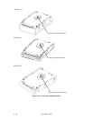
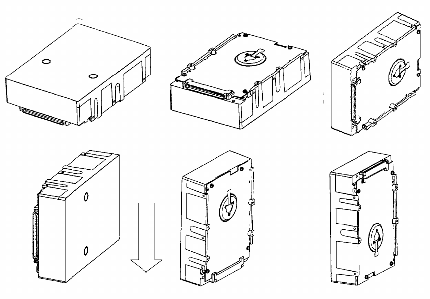
The permissible orientations of the IDD are shown in Figure 4.5, and the tolerance of the angle
is ±5° from the horizontal plane.
Figure 4.5 IDD orientation
4.1.3 Notes on mounting
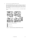
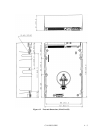
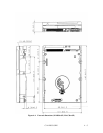
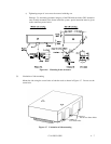
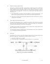
(1) Mounting frame structure
To guarantee integrity of the IDD disk enclosure (DE) insulation once mounted on the frame
inside the system, special attention must be given to the note below.
Note:
Generally, SG and FG are connected at one point in the system enclosure. Therefore, use
following procedure to maintain the insulation when mounting the IDD.
a) Use the frame with an embossed structure or the like to avoid contact between the DE
base and FG. Mount the IDD with making a gap of 2.5 mm or more between the IDD
and the frame of the system.
b) As shown in Figure 4.6, the inward projection of the screw from the IDD frame wall
at the corner must be 4 mm or less.
Direction of
gravity
(a) Horizontal –1 (b) Horizontal –2 (c) Vertical –1
(d) Vertical –2 (e) Upright mounting –1 (f) Upright mounting –2