


C141-E035-02EN 3 - 7
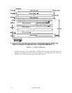
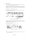
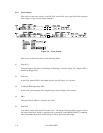
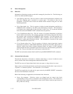
(2) Track skew and cylinder skew
To avoid waiting for one turn involved in head and cylinder switching, the first logical data
block in each track is shifted by the number of sectors (track skew and cylinder skew)
corresponding to the switching time. Figure 3.5 shows how the data block is allocated in each
track.
At the head switching location in a cylinder, the first logical data block in track t + 1 is
allocated at the sector position which locates the track skew behind the sector position of the
last logical data block sector in track t.
At the cylinder switching location, like the head switching location, the first logical data block
in a cylinder is allocated at the sector position which locates the cylinder skew behind the last
logical sector position in the preceding cylinder. The last logical sector in the cylinder is
allocated when formatting, and is an unused spare sector.
Figure 3.5 Track skew/cylinder skew
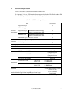
The number of physical sectors (track skew factor and cylinder skew factor) corresponding to
the skew time varies depending on the logical data block length because the track skew and
the cylinder skew are managed for individual sectors. The IDD automatically determines
appropriate values for the track skew factor and the cylinder skew factor according to the
specified logical data block length. The value can be read out by the MODE SENSE or
MODE SENSE EXTENDED command after the track has been formatted.