


C141-E035-02EN 4 - 19
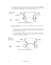
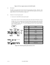
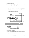
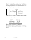
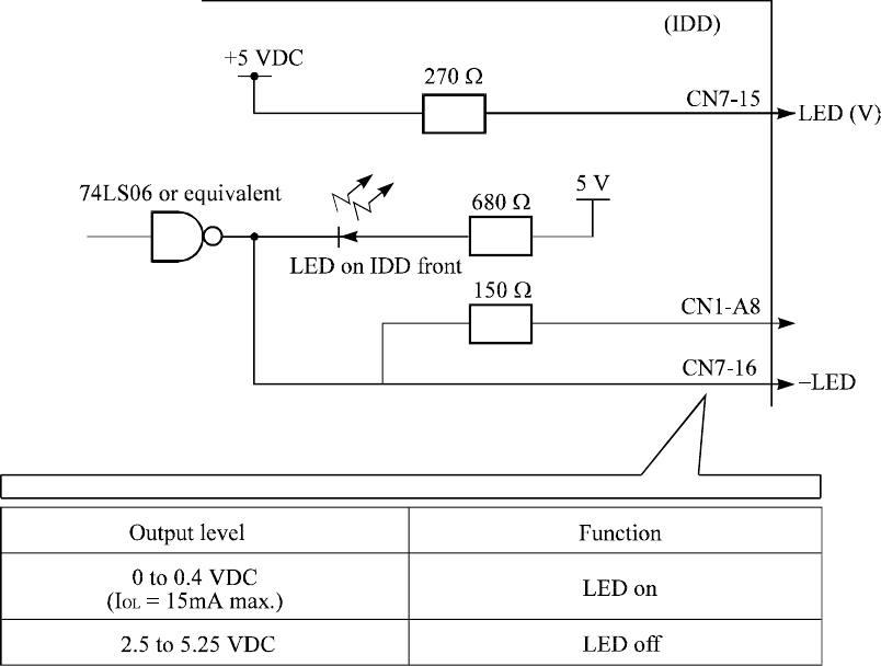
b. –LED and LED (V): Output signals
These signals actuate the external LED as same as LED on the front panel of the disk
drive. The electrical requirements are given in Figure 4.22.
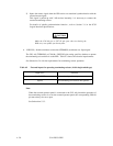
Notes:
1. The external LED is identical in indication to the LED on the front of the IDD.
The meaning of indication can be selected with the CHANGE DEFINITION
command. For details of command, refer to SCSI Logical Interface
Specifications.
2. Any load other than the external LED (see Subsection 4.3.5) should not be
connected to the LED (V) and –LED terminals.
Figure 4.22 Output signal for external LED
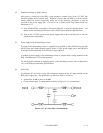
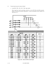
c. -SYNC (-Spindle sync): Input/output signal
The pin CN1-A6, or CN7-10 inputs or outputs the signal for rotational synchronization
when the IDD carries out rotational synchronization.
1) Outputs the master signal for rotational synchronization when the IDD is the master
of rotational synchronization.