


C141-E035-02EN4 - 16
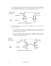
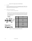
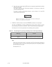
Figure 4.18 Power supply connector (16-bit SCSI model)
(3) SG terminal
The IDD is not provided with an SG terminal (fasten tab) for DC grounding. Therefore, when
connecting SG and FG in the system, use the +5 VDC RETURN (ground) inside the power
supply connector as the SG on the power supply side.
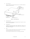
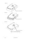
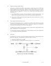
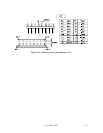
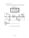
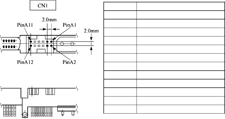
(4) Connector for external operator panel
• Connector for 16-bit SCSI external operator panel
CN1 provides connector for the external operator panel other than the SCSI bus as shown
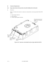
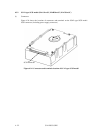
in Figure 4.19. Also, a connector for the external operator panel are provided on the IDD
as shown in Figure 4.20. This allows connection of an external LED on the front panel,
and an SCSI ID setting switch. For the recommended circuit of the external operator
panel, see Subsection 4.3.5.
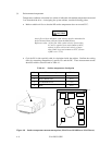
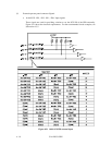
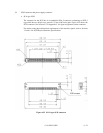
Figure 4.19 External operator panel connector (CN1)
Pin Signal
A1 –ID0
A2 (Reserved)
A3 –ID1
A4 (Open)
A5 –ID2
A6 –SYNC
A7 –ID3
A8 –LED
A9 TERMON
A10 GND
A11 +5 V
A12 (Reserved)