


1 1 Gbit/s Ethernet I/O Module 113
E
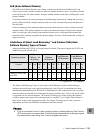
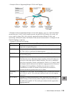
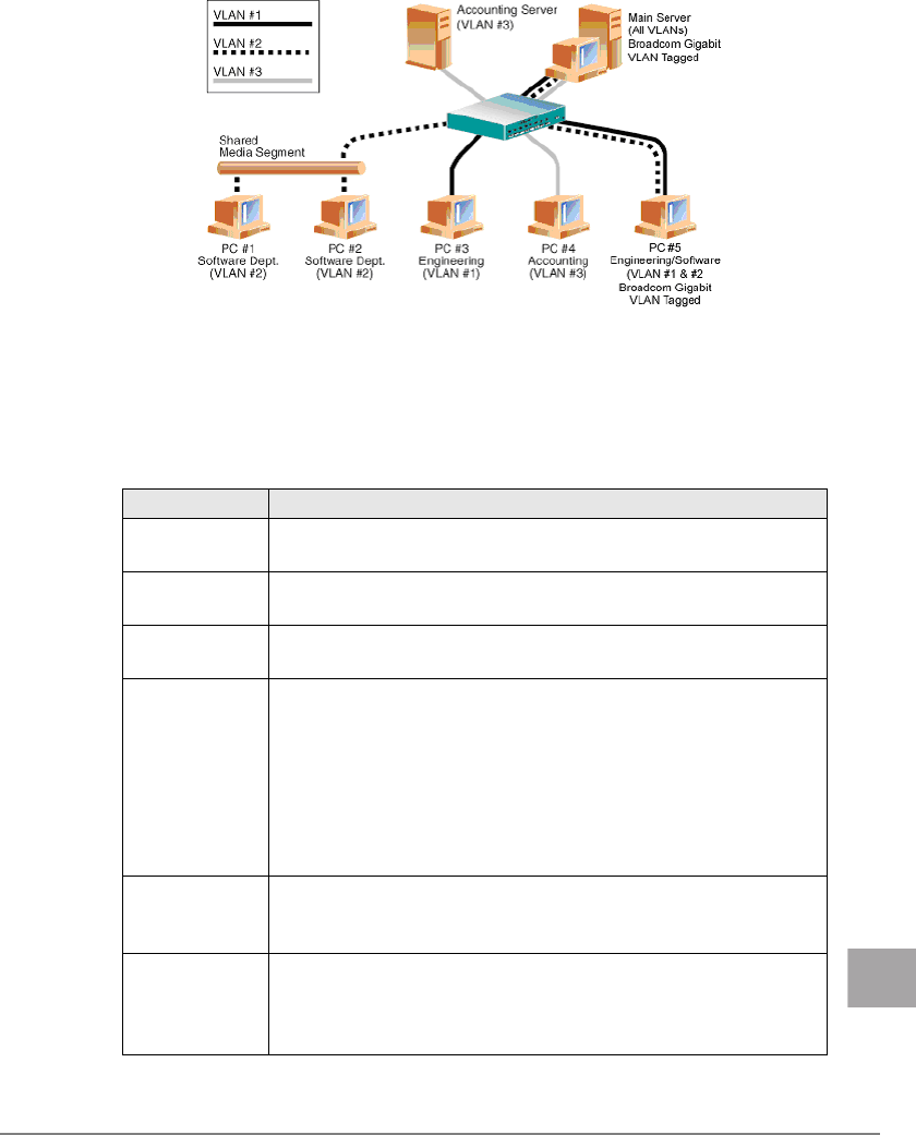
• Example of Servers Supporting Multiple VLANs with Tagging
"• Example of Servers Supporting Multiple VLANs with Tagging" (
Jpg.113)" shows an example
network that uses VLANs. In this example network, the physical LAN consists of a switch, two
servers, and five clients. The LAN is logically organized into three different VLANs, each
representing a different IP subnet. The features of this network are described in "• Example VLAN
Network Topology" (
Jpg.113).
• Example VLAN Network Topology
Component Description
VLAN #1 An IP subnet consisting of the Main Server, PC #3, and PC #5. This subnet
represents an engineering group.
VLAN #2 Includes the Main Server, PCs #1 and #2 via shared media segment, and PC
#5. This VLAN is a software development group.
VLAN #3 Includes the Main Server, the Accounting Server and PC #4. This VLAN is
an accounting group.
Main Server A high-use server that needs to be accessed from all VLANs and IP subnets.
The Main Server has a Broadcom adapter installed. All three IP subnets are
accessed via the single physical adapter interface. The server is attached to
one of the switch ports, which is configured for VLANs #1, #2, and #3. Both
the adapter and the connected switch port have tagging turned on. Because of
the tagging VLAN capabilities of both devices, the server is able to
communicate on all three IP subnets in this network, but continues to
maintain broadcast separation between all of them.
Accounting
Server
Available to VLAN #3 only. The Accounting Server is isolated from all traffic
on VLANs #1 and #2. The switch port connected to the server has tagging
turned off.
PCs #1 and #2 Attached to a shared media hub that is then connected to the switch. PCs #1
and #2 belong to VLAN #2 only, and are logically in the same IP subnet as
the Main Server and PC #5. The switch port connected to this segment has
tagging turned off.