


8
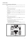
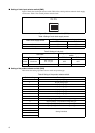
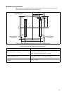
■ Setting of clock input selector switch (SW2)
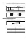
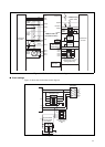
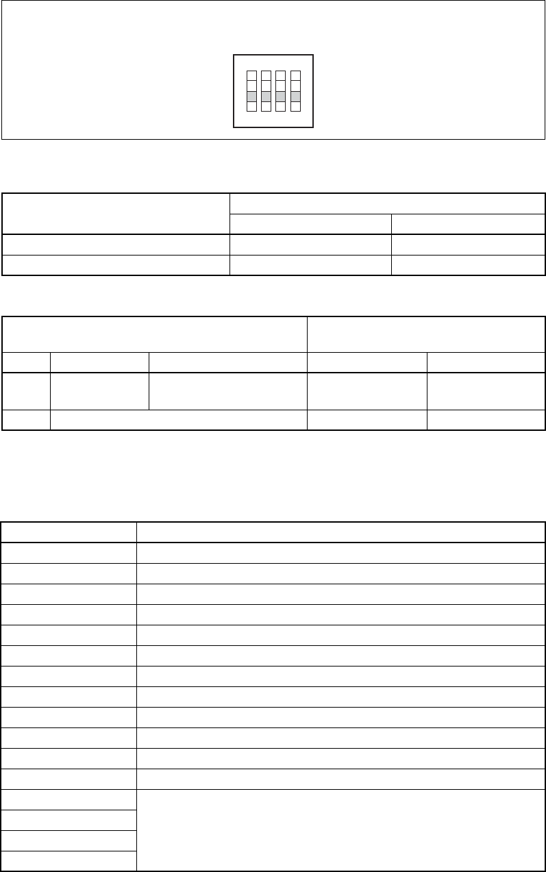
Figure 9 shows the clock input selector switch. Table 4 lists switch positions and main clock supply
clock source. Table 5 lists switch positions and sub clock.
Figure 9 Clock input selector switch (SW2)
Table 4 Setting of main clock supply source
Table 5 Setting of sub clock
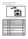
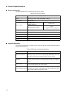
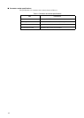
■ Setting of the product selector switch (SW3)
Table 6 lists the setting of product selector switch and product type.
Table 6 Setting of the product selector switch
Main clock supply source
Settings of the clock input selector switch
SW2-1 SW2-2
Clock area OFF OFF
User system ON ON
Sub clock
Settings of the clock input selector
switch
Used Supply source M1 correspondence pin SW2-3 SW2-4
enable Clock area
X0A : R3 pin
X1A : V1 pin
OFF OFF
disable - ON ON
Switch setting Product type
0 100-pin package type
1 80-pin package type
2 64-pin package type
3 48-pin package type
4 32-pin package type
5 28-pin package type
6 20-pin package type
7 Setting Prohibited
8 100-pin package , LCD function integrated type
9 80-pin package , LCD function integrated type
A 64-pin package , LCD function integrated type
B 48-pin package , LCD function integrated type
C
Setting Prohibited
D
E
F
X0
X1
X0A
X1A
1 2 3 4
ON