


9
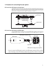
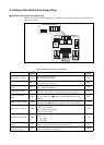
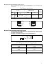
■ Setting of the sub clock selector jumper plug (S1)
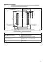
Table 7 lists jumper plug positions and sub clock selection. Figure 10 shows the examples of sub
clock selection.
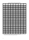
Table 7 Setting of sub clock selector
* : Oscillation is not guaranteed when the crystal oscillator is mounted on the user system.
Figure 10 The example of sub clock selection
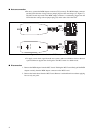
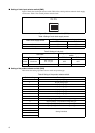
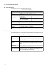
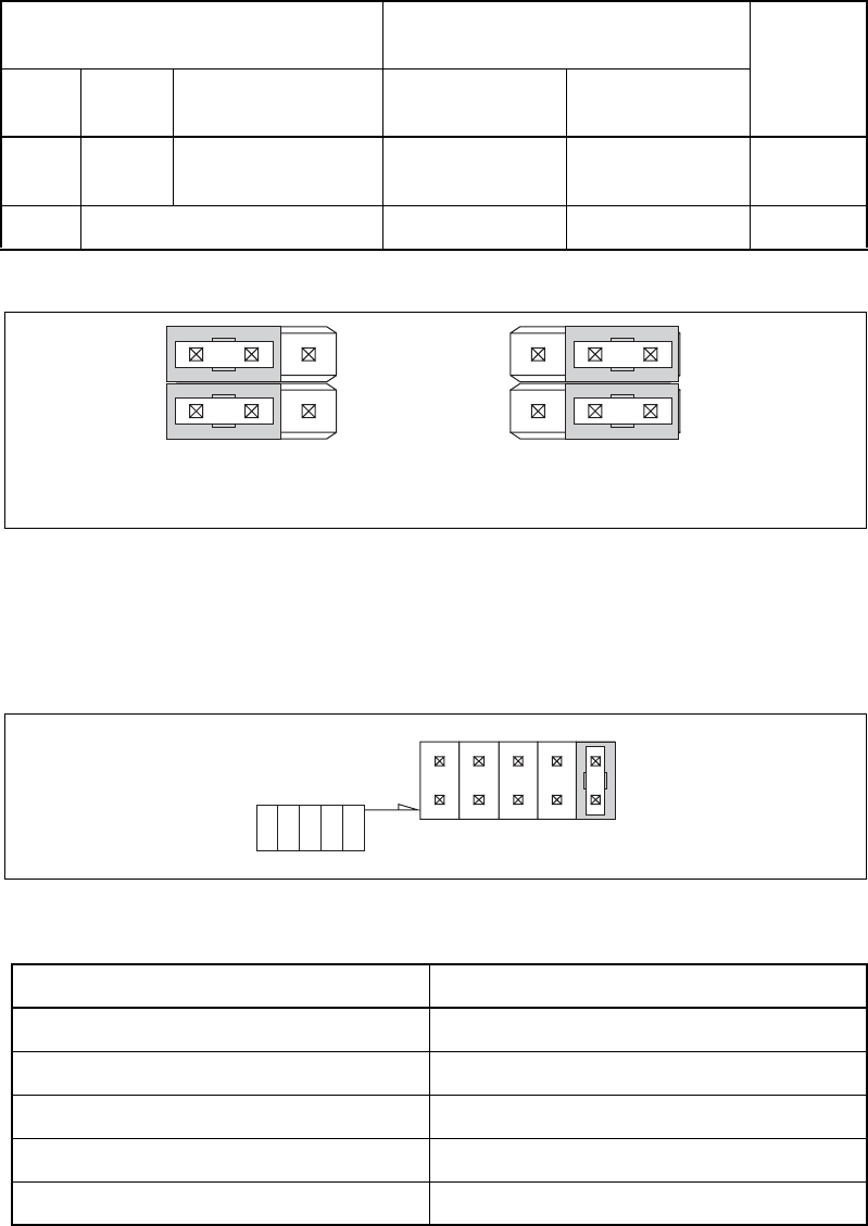
■ Settings of the LVD2 detection voltage jumper plug (S2)
Figure 11 shows the settings of the LVD2 detection voltage jumper plug (S2). Table 8 lists jumper
plug positions and detection voltages.
(This setting is not available, when debugging. Please use with LVD0 setting.)
Figure 11 The LVD2 detection voltage jumper plug (S2)
Table 8 Setting of the LVD2 detection voltage jumper plug
Sub clock
Settings of the sub clock selector
jumper plug (S1)
Example
of settings
Used
Supply
source *
M1 correspondence
pin
X0A X1A
enable
Clock
area
X0A : R3 pin
X1A : V1 pin
Jumper of 1:B - 1:C Jumper of 2:B - 2:C Example 1
disable ⎯ Jumper of 1:A - 1:B Jumper of 2:A - 2:B Example 2
Jumper plug points LVD2 setting value
LVD0 + 4.17 V
LVD1 + 3.74 V
LVD2 + 3.3 V
LVD3 + 2.9 V
LVD4 + 2.6 V
C B A
1
2
C B A
1
2
Example 1
Example 2
LVD4
LVD3
LVD2
LVD1
LVD0