


5
4. How to setup
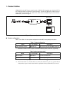
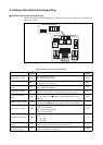
■ How to the switch and jumper plug on a MCU board setup
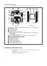
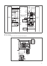
Please set the following switches referring to “Figure 6 The switch and jumper plug on a MCU
board”.
1. Set the clock selector switch (SW1-1) to ON or OFF to disable or enable the sub clock, respec-
tively.
2. Set the C-pin selector switch (SW1-4) to ON.
3. Set the clock input selector switch (SW2).
Check that value with “5. Setting of the Switch and Jumper Plug ■ Setting of clock input selector
switch (SW2)”.
4. Set the product selector switch (SW3) to the value corresponding to the number of pins on the
production MCU.
Check that value with “5. Setting of the Switch and Jumper Plug ■ Setting of the product selector
switch (SW3)”.
5. Set the LVD selector switch (SW4) to LVD1 or OFF to enable or disable the sub clock, respec-
tively.
6. Set the power supply selector switch (SW5) to 5 V.
7. Set the sub clock selector jumper plug (S1).
Check that value with “5. Setting of the Switch and Jumper Plug ■ Settings of the sub clock se-
lector jumper plug (S1)”.
Please use with following settings, so APB8 bus and LVD2 functions are not available.
• Set (SW1-2) to OFF (For reservation bit).
• Set the APB8 bus output selector switch (SW1-3) to OFF.
• Set the LVD2 detection voltage jumper plug (S2) to LVD0.
Check that value with “5. Setting of the Switch and Jumper Plug ■ Settings of the LVD2 de-
tection voltage jumper plug (S2)”.
Figure 6 The switch and jumper plug on a MCU board
BGM
ADAPTER
SUB CLOCK
C B A
1
2
CLK
CLK S.V.
APB8
C
X0
X1
X0A
X1A
7
6
5
4
3
2
1
0
F
E
D
C
B
A
9
8
PRODUCT SELECT
LVD4
LVD3
LVD2
LVD1
LVD0
GND
VCC
3V
5V
LVD2OFFLVD1
MAIN CLOCK
1 2 3 4 1 2 3 4
ON ON
SW5
SW4
SW2
SW1
SW3
S2
S2
SC2SC3
SC1SC4
SC6
SC5