


2
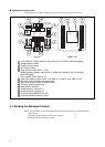
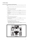
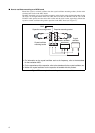
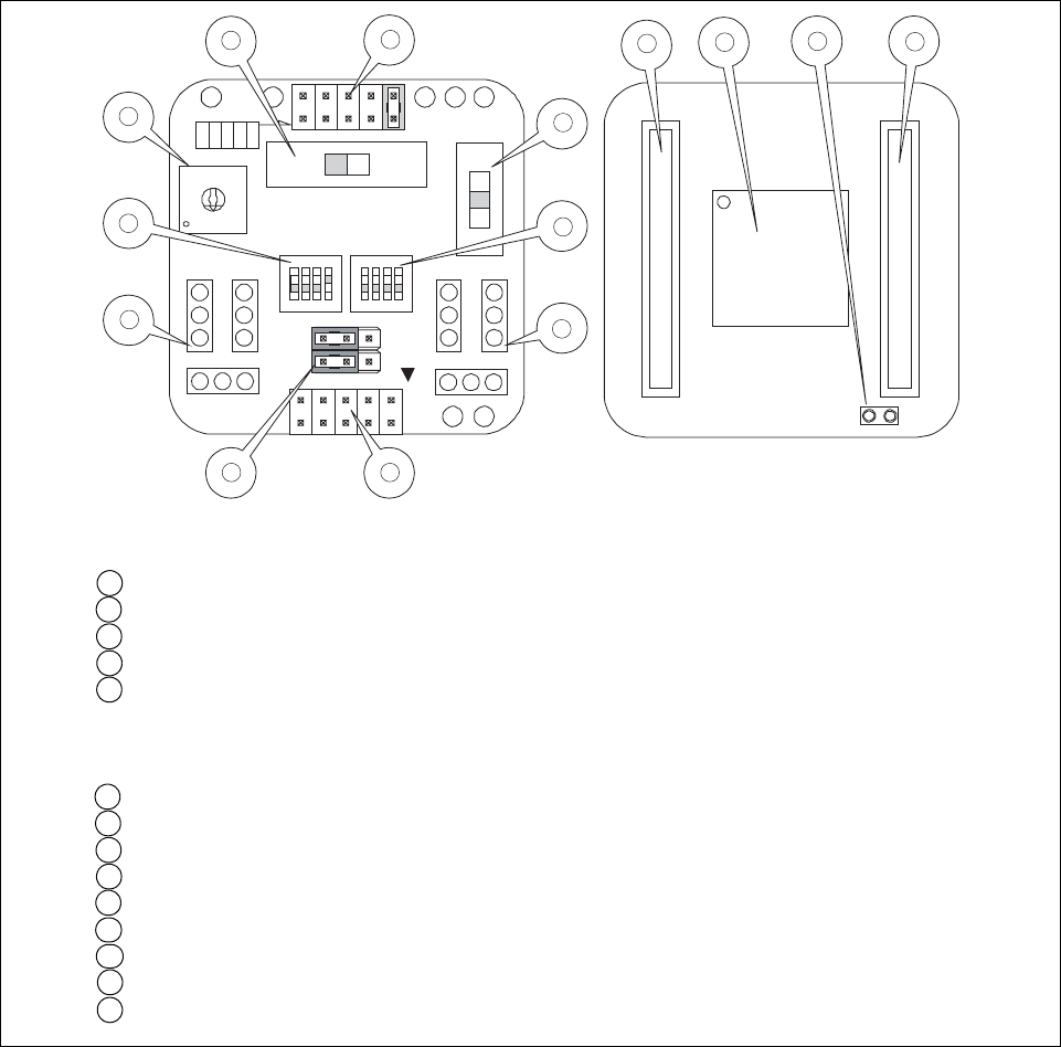
■ Appearance and part name
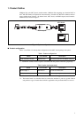
The appearance of a MCU board and the name of each part are shown in Figure 2.
Figure 2 MCU board appearance figure
2. Checking the Delivered Product
Before using the MCU board,confirm that the following components are included in the box:
• MCU board : 1
• Operation manual (English version, this manual) : 1
• Operation manual (Japanese version) : 1
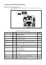
BGM
ADAPTER
SUB CLOCK
C B A
1
2
CLK
CLK S.V.
APB8
C
X0
X1
X0A
X1A
7
6
5
4
3
2
1
0
F
E
D
C
B
A
9
8
PRODUCT SELECT
LVD4
LVD3
LVD2
LVD1
LVD0
GND
VCC
3V5V
LVD2OFFLVD1
MAIN CLOCK
1 2 3 4 1 2 3 4
ON ON
HEADER I/F CONNECTOR A
HEADER I/F CONNECTOR B
1
2
3
4
5
6
7
8
9 10
11
12
13
14
1 LVD2 detection voltage selector jumper plug (it is not available, when debugging)
2 Voltage selector switch
3 Product selector switch
4 LVD selector switch
5 Clock selector switch (SW1-1: CLK)
APB8 bus output selector switch (SW1-3: APB8) (for extension) (it is not available,
when debugging)
C-pin selector switch (SW1-4: C)
6 Clock input selector switch (SW2-1: X0, SW2-2: X1, SW2-3: X0A, SW2-4: X1A)
7 Sub clock crystal oscillator mounting socket
8 Main clock crystal oscillator mounting socket
9 Sub clock selector jumper plug
10 BGM adapter connector
11 Header board I/F connector A
12 Header board I/F connector B
13 Evaluation MCU (MB95FV100-103)
14 Incorrect insertion prevention guard
Top view
Bottom view