


3
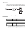
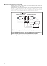
3. Procedure for connecting the user system
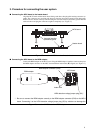
■ Connecting the MCU board to the header board
Align the MCU board and the header board facing each other, then plug their mating connectors to-
gether. The connectors are provided with incorrect insertion prevention guards located diagonally.
Position the two boards correctly without letting the incorrect insertion prevention guards interfere
with each other and plug the connectors together completely (see “Figure 3”).
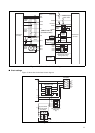
Figure 3 Connection of MCU board and header board
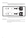
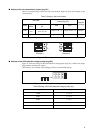
■ Connecting the MCU board to the BGM adapter
Connect the BGM adapter to the MCU board. Plug the BGM adapter's interface connector deep into
the BGM adapter connector on the MCU board with their index marks (▼) aligned (see “Figure 4”).
Figure 4 Connection of MCU board and BGM adapter
MCU board
Incorrect insertion
prevention guard
Header board
M2146-09
BGM
ADAPTER
SUB CLOCK
C B A
1
2
CLK
CLK S.V.
APB8
C
X0
X1
X0A
X1A
7
6
5
4
3
2
1
0
F
E
D
C
B
A
9
8
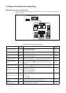
PRODUCT SELECT
LVD4
LVD3
LVD2
LVD1
LVD0
GND VCC
3V5V
LVD2OFFLVD1
MAIIN CLOCK
1 2 3 4 1 2 3 4
ON ON
MCU board
Index mark
LVD2 detection voltage jumper plug (S2) *
BGM adapter
BGM adapter connector (CN3)
* : Be sure to connect the BGM adapter correctly to the BGM adapter connector (CN3) on the MCU
board. Connecting it to the LVD2 detection voltage jumper plug (S2) by mistake can damage the