


4
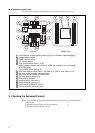
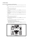
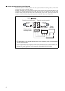
■ Note on connection
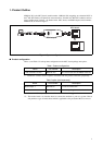
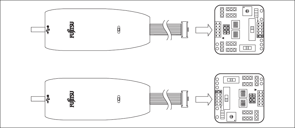
• Be sure to connect the BGM adapter connector (CN3) correctly. The BGM adapter connector
and the LVD2 detection voltage selector jumper plug have the same shape (see “Figure 5”).
The MCU board may break if the BGM adapter connector is accidentally plugged into the
LVD2 detection voltage selector jumper plug (S2) on the other side of the board.
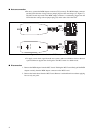
Figure 5 Connection direction of BGM adapter
• To supply a main clock signal from the user system, make an oscillation circuit on the user
system such that it supplies the clock signal to the MCU board via a buffer circuit.
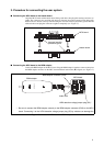
■ Disconnection
1. Remove the BGM adapter from the MCU board. Holding the MCU board firmly, pull the BGM
adapter vertically from the BGM adapter connector on the MCU board.
2. Remove the header board from the MCU board. Remove it with uniform force without applying
force to only one point.
MB2146-09
BGM
ADAPTER
SUB CLOCK
C B A
1
2
CLK
CLK S.V.
APB8
C
X0
X1
X0A
X1A
7
6
5
4
3
2
1
0
F
E
D
C
B
A
9
8
PRODUCT SELECT
LVD4
LVD3
LVD2
LVD1
LVD0
GND
VCC
3V5V
LVD2OFFLVD1
MAIN CLOCK
1 2 3 4 1 2 3 4
ON ON
MB2146-09
BGM
ADAPTER
SUB CLOCK
C B A
1
2
CLK
CLK S.V.
APB8
C
X0
X1
X0A
X1A
7
6
5
4
3
2
1
0
F
E
D
C
B
A
9
8
PRODUCT SELECT
LVD4
LVD3
LVD2
LVD1
LVD0
GND
VCC
3V5V
LVD2OFFLVD1
MAIN CLOCK
1 2 3 4 1 2 3 4
ON ON
OK
NG