


15
■ Header board specifications
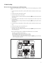
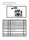
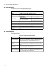
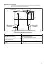
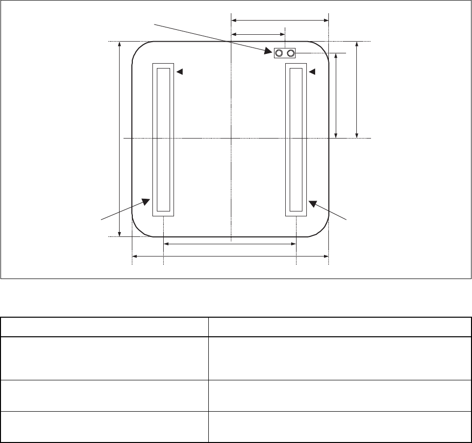
Figure 14 shows recommended dimensions of the header board connected to the MCU board.
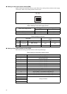
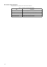
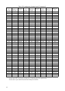
Table 14 lists general specifications of the header board.
Figure 14 Recommended dimensions of the header board (Top view)
Table 14 general specifications of the header board.
Item Description
MCU board interface connector
120 pin 0.5 mm pitch 2 piece connector (Straight) × 2
Model number: WR-120SB-VF-N1
(Japan Aviation Electronics Industry, Limited)
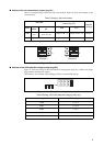
Incorrect prevention guard
2 pin SIP socket
Model number: PCW-3-1-1PW (MAC EIGHT)
Spacing between the MCU and header boards when
engaged
Approx. 5.0 mm
1212
119120119120
MCU board I/F
connector B
MCU board I/F
connector A
30 mm
40 mm
20 mm
40 mm
18 mm
20 mm
13 mm
Incorrect insertion
prevention guard