1. OPERATION
2
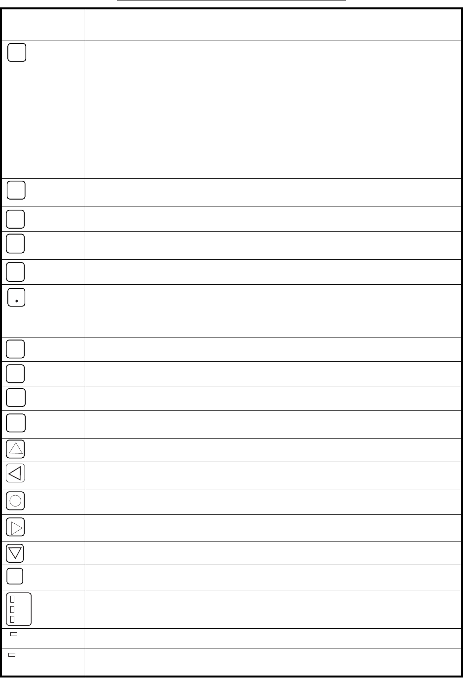
Control description (con’t from previous page)
Control,
indicator
Description
• Enables a setting mode (in combination with numeric key). Press the key fol-
lowed by appropriate numeric key to choose setting mode.
1- Chooses internal or external receiver.
2- Sets timer reception functions.
3- Sets sleep timer.
4- Adds or edit channels.
5- Sets date and time.
6- Sets ISB shift.
7- Adjusts LCD contrast.
9- Clears RAM.
• Returns to top page in setting mode.
• Changes from channel mode to frequency mode.
• Sets frequency in frequency mode.
Adjust LCD brilliance and LED brightness, in five levels.
• Changes from frequency mode to channel mode.
• Sets channel in channel mode.
Chooses recording speed.
• Reverses recording format (from black on white to white on black and vice
versa).
• Inserts decimal point when entering frequency, asterisk when entering channel.
• Chooses + or -.
Chooses IOC (Index of Cooperation).
Starts and stops recording in manual recording.
Confirms setting.
• Clears data in setting mode.
• Switches from setting mode to standby mode.
Raises channel in channel mode, or raises frequency in frequency mode.
Manual phasing (leftward) in recording. Each press shifts the recording leftward
by about 5 mm.
Displays date and time.
Manual phasing (rightward) in recording. Each press shifts the recording right-
ward by about 5 mm.
Lowers channel in channel mode, or lowers frequency in frequency mode.
Feeds paper.
The top, middle or bottom LED lights when the receive frequency is higher, the
same or lower than programmed frequency, respectively.
Lights when the timer mode or sleep mode is active.
• Flashes when receiving start signal.
• Lights when recording is in progress.
PR
G
FRQ
DIM
CH
SPD
RE
V
IOC
RC
D
E
C
2
4
5
6
8
0
TUNE
TIMER
R
C
D


