7. INSTALLATION
7-6
JIS cable specifications
Inner Conductor Insulation Outer Conductor Jacket
Braid
Type
Stranding
(No./mm)
Dia.
(mm)
Thick
(mm)
Dia
(mm)
Dia./
Pitch
Dia.
(mm)
Thick
(mm)
Dia.
(mm)
Cond.
resistance
(Max.)
(20°C)
(Ω/km)
Nominal
attenuation
10 MHz
(dB/km)
Capa-
citance
(pF/m)
Approx.
mass
(kg/km)
3C-2V 1/0.5
0.5 1.3 3.1 0.14/5/24 26 3.8 0.8 5.4±0.5 91.4 42 67±3 42
5C-2V 1/0.8
0.8 2.05 4.9 0.14/7/24 42 5.7 0.9 7.4±0.5 35.9 27 67±3 74
7C-2V 7/0.4
1.2 3.05 7.3 0.18//8/24 45 8.2 1.1 10.4±0.5 20.7 22 67±3 140
5D-2V 1/1.4
1.4 1.7 4.8 0.14/7/24 42 5.5 0.9 7.3±0.5 11.7 27 100±4 80
7.4 Supplying Power to the Preamp Unit
The preamp unit is powered with 12 VDC power fed from the facsimile receiver.
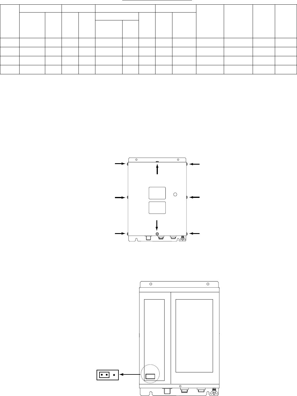
To power the preamp unit, do the following:
1. Disconnect the power cable from the FAX-30.
2. Unfasten eight screws marked with the arrows below to remove the cover.
FAX-30, top view
3. Set the jumper block J23 in the “ACT(IVE)” position. See the figure below for
the “ACT” position.
MAIN Board 08P3218
RCV Board 08P3219
J23
ACT WIRE
J23
FAX-30, top view, cover removed
4. Close the cover and connect the power cable.


