


Magnum 6K25e Gigabit Fiber Switch Installation and User Guide (10/07)
28
www GarrettCom com
..
D D
C
C
B B A A
D D C
C
B B A A
D D
C
C
B B A A
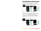
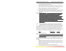
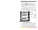
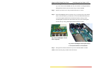
Standard Flush
Mount Bracket
Mid-Range Mount or
5” Set-Back Bracket
Rear Mount Bracket
package, along with the necessary screws for attaching the brackets to the sides of the
Magnum Switch unit. They must be ordered as line items.
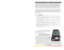
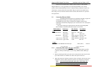
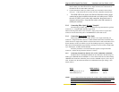
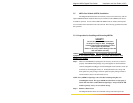
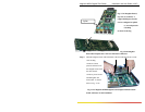
3.3.2 Rack-mounting, Reverse version of the Magnum 6K25es
The optional Reverse Magnum 6K25e Model has all of the cabling (Ethernet
cabling, power cabling and console port cabling) connectors in the rear, and the status
LEDs in the front. The status LEDs that are co-incident with the ports are still present
there, and a second or dual set of LEDs are used for status visibility in the front of the
unit, showing the same data.
There are three options of brackets available to mount in the standard 19”
frame or the 23” frame or ETSI (21”) frame. The 19” brackets are included with each
unit, the other two may be purchased if desired.
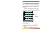
With each bracket type, there are three different mounting options is shown in
Fig. 3.3.2. The case of the Magnum 6K25e has mounting holes prepared for each of the
mounting arrangements. Users may choose the mounting arrangement most suitable for
their
installation
.
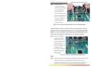
Fig
3.3.2
Reverse
Magnum
6K25e
units,
rack-
mounted
in a frame
3.4
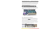
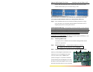
Powering the Magnum Managed Fiber Switch
The Magnum 6K25e Switches incorporate an internal universal power supply
and have a recessed male IEC connector for the AC power cord at the left-rear. A
manual power ON-OFF switch is adjacent. A six-foot 115 VAC 60 Hz standard power
cord is supplied with each unit shipped within the United States and Canada.
The auto-ranging power supply supports installation environments where the
AC voltage is from 90 to 260 volts with a power input frequency between 47 and 63 Hz.
The 25-port units will consume over 20 watts of power typically. When connecting the