Magnum 6KQ Managed Field Switch Installation and User Guide (04/07)
25
www GarrettCom com
..
fiber optic segment.
3. Find the Transmit (TX) and Receive (RX) markings on the SFP transceiver to
verify the top side of it. Some of the transceiver marks arrow sign for up.
4. Position the SFP transceiver correctly before insertion, and then insert the SFP
transceiver carefully, until the transceiver connector snap into the place in the socket
connector.
5. Connect the Transmit (TX) port on the Magnum PM to the Receive (RX) port of the
remote device. Connect the Receive (RX) port on the PM to the Transmit (TX) port of
the remote device.
The LINK LED on the front of the PM will illuminate and turn Green, when a proper
connection has been established at both ends (and when power is ON in the unit). If
LINK is not lit or OFF after cable connection, the normal cause is improper cable
polarity. Swap the fiber cables at the PM
connector and also check the connectivity on
the target device to remedy this situation.
Reconfigure or reboot both the device if
required.
If connected properly, you can check via
(MNS-6K)software too for verification the
validity of SFP Gigabit ports.
Make sure Rel 3.6 or higher firmware is
loaded on the 6KQ switches to support the
SFP transceivers.
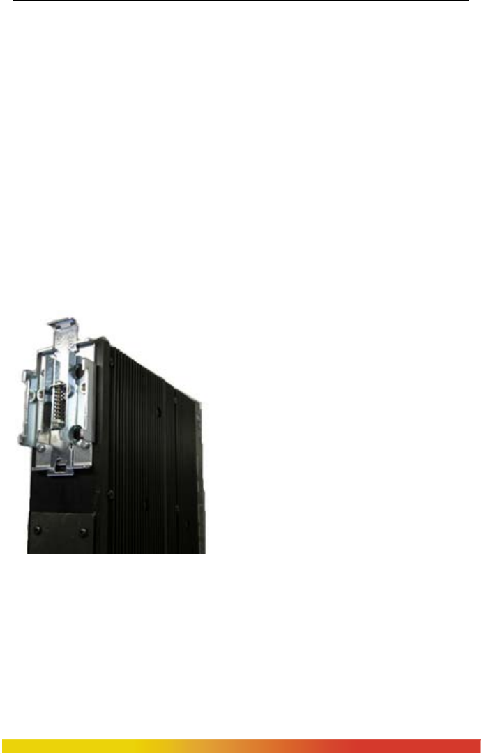
3.3 DIN-Rail Mounting the Magnum 6KQ
The Magnum 6KQ is designed for use in a “factory floor” industrial
environment. It is available with optional DIN-Rail brackets to mount it securely in a
metal factory floor enclosure, maintained vertically for proper convection cooling of the
unit. The Magnum 6KQ requires one DIN-Rail mounting clip or latch for secure
mounting. These may be ordered as Model # DIN-RAIL-6KQ. See a 6KQ viewed from
the side, at the left, with model DIN-RAIL-6KQ in place on the unit.


