


Magnum 6KQ Managed Field Switch Installation and User Guide (04/07)
28
www GarrettCom com
..
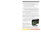
consumption will range from about 20 up to 35 watts, depending on the port quantity and
types in the configuration.. When connecting the Ethernet cabling, there is no need to
power down the unit. Individual cable segments can be connected or disconnected
without concern for power-related problems or damage to the unit.
Power input options are available to suit the 6KQ Switches to special high-
availability communications and/or heavy industrial-grade applications, including:
* -48VDC, 24VDC and 125VDC with single DC input,
* -48VDC, 24VDC and 125VDC with dual-source DC input
External AC power supplies are optional, see Section 1.2, Ordering Information.
See the Appendices of this manual for more details. Use an RFQ for other variations.
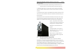
3.5 Alarm Contacts for monitoring internal power, and Software Traps
The Alarm Contacts feature, standard on Magnum 6KQ’s, provides two
Form C Normally Closed (NC) contacts to which the user can attach two sets of status
monitoring wires at the green terminal block. When this option is present, the terminal
block for Alarm Contacts is part of the Power Input panel in the 6KQ case. The DC
power input connection is in the same panel.
The first NC Alarm Contact (top position, switch vertically mounted) is a
“Software Alarm”, operated by user settings in the MNS-6K software. The user can
disable the Software Alarm feature with a software configuration command if desired.
When the Software Alarm is enabled, the Form C Normally Closed (NC) contact is held
close during normal software operation. A user-defined software malfunction, such as an
SNMP Trap or a Software Security violation or an S-Ring Fault, causes the contact to
open and thus triggers an alarm in the user’s monitoring system
The second NC Alarm Contact is held closed when there is power on the
main board inside of the Switch. This provides a “Hardware Alarm” because the NC
contacts will open when internal power is lost,
either from an external power down condition
or by the failure of the power supply inside of
the Magnum Switch.
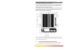
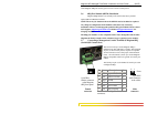
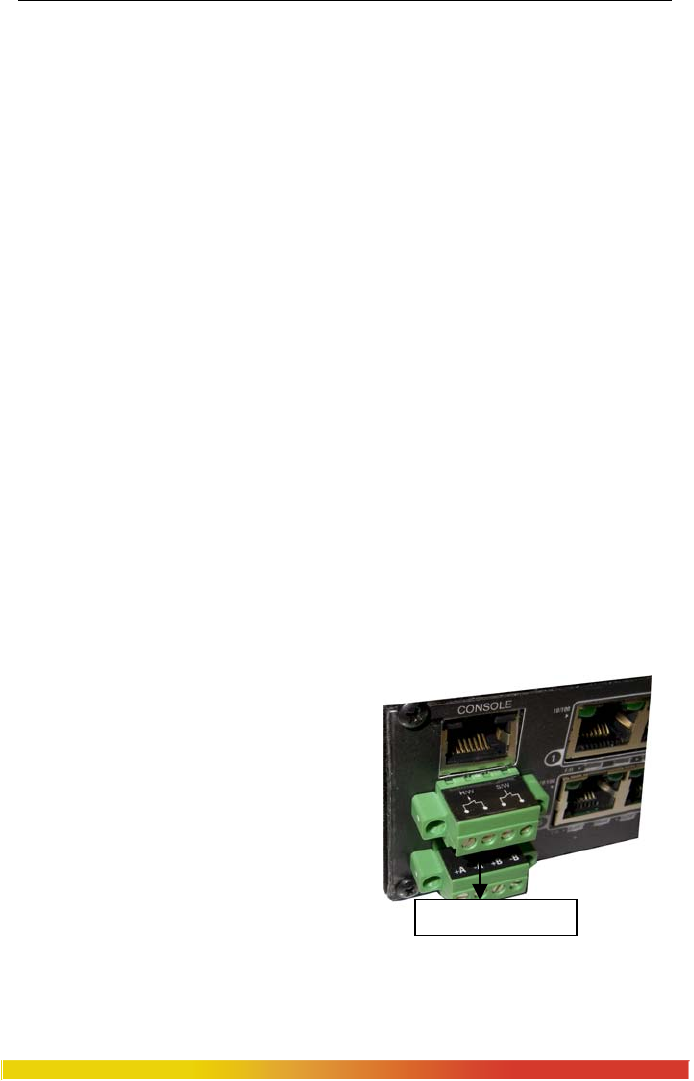
Useful info. about Alarm
contacts:
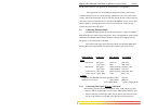
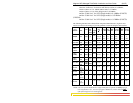
1. There are four terminal blocks (1,2,3,4)
provided next to the DC power supply
2. The top two pins (1,2) are software operated
3. The bottom two pins (3,4) are hardware
operated
4. These are both NC (normally closed) relays
5. The switch’s software operation needs to be enabled and set to get the Alarm traps. For
detailed information about the Software Alarm and software control of SNMP alarm
traps, please reference the Magnum MNS-6K Software User Manual. (Chapter 19).
Rela
y
Contacts