


Magnum 6KQ Managed Field Switch Installation and User Guide (04/07)
30
www GarrettCom com
..
The Hyper terminal configuration is exactly the same as all other 6K-Family managed
switches. Please check the following URL for details-
http://www.garrettcom.com/techsupport/software/userguides/mns6k_CLI.pdf
NOTE: The console RJ-45-Serial cable may be ordered from the GCI factory, using the
model number and description here:
CONSOLE-CBLQD- Console attachment cable serial null-modem cable with one side
RJ-45 for the 6KQ and a male DB-9 Female connector on the other end.
CONSOLE-CBLQU- Console attachment cable serial null-modem cable Combo with
one serial- RJ-45 for the 6KQ side and a USB cable connector option on the other end
(e.g computer).
NOTE for Power Substations
: In support of the IEEE 1613 Class 2 standard, GCI
advises that, for substation applications, the serial RJ-45console ports are
intended for temporary connectivity to other equipment such as PCs. Since the
console port connection is temporary, it is excluded from IEEE 1613 packet-
loss testing per the 1613 standard-defined test procedure.
4.0 OPERATION
This chapter describes the functions and operation of the Magnum 6KQ
Switch.
4.1 Switching Functionality
A Magnum 6KQ provides switched connectivity at Ethernet wire-speed among
all of its ports. The Magnum 6KQ supports10/100Mbs for copper media and 10 or
100Mb separate traffic domains for fiber ports to maximize bandwidth utilization and
network performance. All ports can communicate to all other ports in a Magnum 6KQ,
but local traffic on a port will not consume any of the bandwidth on any other port.
The Magnum 6KQ units are plug-and-play devices. There is no software
configuring necessary to be done for basic operation at installation or for maintenance.
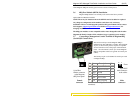
The only hardware configuration settings are user options for an UP-LINK Switch
(resides inside the unit) on the 6KQ-RJ45. There is an optional Half / Full duplex mode
and 10Mbps or 100Mbps selection for the switched ports which must be configured
through MNS software per unit as per the requirement. The internal functions of both are
described below.
Filtering and Forwarding
Each time a packet arrives on one of the switched ports, the decision is taken to
either filter or to forward the packet. Packets whose source and destination addresses are
on the same port segment will be filtered, constraining them to that one port and relieving
the rest of the network from having to process them. A packet whose destination address
is on another port segment will be forwarded to the appropriate port, and will not be sent