


Magnum 6KQ Managed Field Switch Installation and User Guide (04/07)
29
www GarrettCom com
..
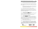
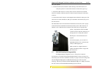
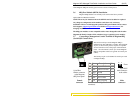
The Alarm Contacts are on the front left area (next to the DC power source)
of the Magnum 6KQ unit and are green in color as shown in the picture.
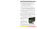
3.6 6KQ Port Module (6KPM) Installation
Magnum 6KQ Switches are normally received from the factory with all
required 6K Port Modules installed.
NOTE: There may be situations where the 6K PMs need to be added or replaced.
Any change in configuration of the modules can be done only via factory
installation. There is no field upgrade option for 6KQ port modules. Please contact
Tech Support (support@garrettcom.com
) / RMA(rma@garrettcom.com) for
changing modules.
The 6KQ port modules are not compatible with or inter-changeable with the other
Magnum 6K-Family Switches’ PMs, which use larger (typically 8-port) modules.
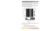
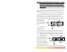
3.7 Connecting a Management Console Terminal to Magnum 6KQ
(Serial-RJ45 Console Port)
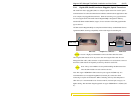
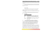
The serial console port on the Magnum 6KQ is
different from other 6K-family switches. The Serial RJ-
45 port, as shown in the picture, requires an 8-pin RJ-
45 male connector to have the proper communication.
(Note - the serial RJ-45 console port on the Magnum
6KQ is compatible with Cisco-type RJ-45 console port
cables).
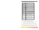
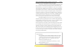
The Serial port pin-out for the RJ-45 console port used
on Magnum 6KQ
8 pin RJ45
female connector
at the Magnum
6KQ front panel
8 pin RJ45
male connector
at the cables
Female
connector
Pin-out info for 6KQ (RJ-45 female
connector).
Pin Name Description Dir
1 RTS Request To Send OUT
3 TXD Transceiver Data OUT
4 GND Ground -
5 GND Ground -
6 RXD Receive Data IN
8 CTS Clear To Send IN
Male
connector
8 1
8 1
Fron
t