


Magnum 6KQ Managed Field Switch Installation and User Guide (04/07)
47
www GarrettCom com
..
other communication companies. In addition, many high availability equipment services,
such as broadcasters, publishers, newspaper operations, brokerage firms and other
facilities often use a battery backup system to maintain operations in the event of a power
failure. It is also frequently used for computer system backup, management and
operations monitoring equipment.
The 24V and 125VDC options are particularly useful in the industrial environment,
where it is common for facilities to operate on 24VDC or 125VDC power. The 125VDC
options are mainly used in power utilities, such as electrical substations, electrical
generating plants, etc. The 24VDC applications are mainly in heavy duty industrial
automation such as factory floor, process plants, HVAC, military equipment, etc.
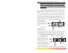
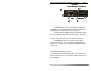
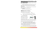
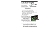
B4.0 6KQ, -48V, 24, 125VDC INSTALLATION
This section describes the proper connection of the -48VDC leads (or 24VDC /
125VDC leads) to the DC power terminal block on the Magnum 6KQ Switch. The DC
terminal block on the Magnum 6KQ Managed Switch is located on the left front of the
unit and is equipped with four (4) screw-down lead posts. The power terminals are
identified as positive (+) and negative (-), and they are electrically floating inside the unit
so that either may be grounded by the user if desired. The chassis is “earth” or ground
(GND).
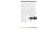
The connection procedure is straightforward. Simply insert the DC leads to the
Switch’s power terminals, positive (+) and negative (-) screws. The use of Ground
(GND) connects to the Switch chassis screw provided under the DC terminal. Ensure that
each lead is securely tightened.
NOTE: Always use a voltmeter
to measure the voltage of the incoming power supply
and figure out the +ve potential lead or -ve potential lead. The more +ve potential lead
will connect to the post labeled “+ve” and the rest to the “-ve”. The GND can be
hooked up at the last.
When power is applied, the green PWR LED will illuminate.
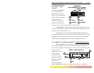
Note: The GND should be hooked up first. The 6KQ unit has a floating ground, so the
user may elect to Ground either + or = terminal to suit the customer’s use.
Before connecting hot lines to the Terminal Block of –48VDC, 24VDC or
125VDC, always use a digital voltmeter to measure the output voltage of the power
supply and determine the lead which is more “+ve potential”. The more “+ve” voltage
lead from 48V or –48V supply must be connected to the post labeled “+”.
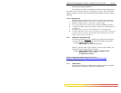
B4.1 UL Requirements for DC-powered units
1. Minimum 18AWG cable for connection to a Centralized DC power source.
2. Minimum 14AWG cable for connection to a earthing wiring.
3. Use only with Listed 10 A circuit breaker provided in building installation.
4. “Complies with FDA radiation performance standards, 21 CFR subchapter J.”
or equivalent.
5. Fastening torque of the lugs on the terminal block: 9 inch-pound max.
6. Centralized DC Power Source cable securement, use at least four cable ties to