


6 MULTILINK ETHERNET COMMUNICATIONS SWITCH – QUICKSTART GUIDE
QUICKSTART GUIDE
The DIN-Rail mounting brackets and latches are optional and need to be ordered as
separate items.
2.3.1 Mounting Dimensions with Metal Brackets
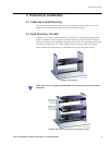
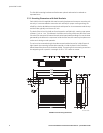
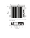
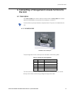
Each MultiLink Unit is supplied with metal mounting brackets and screws to mount the unit
securely. It is recommended to mount the Unit vertically for proper cooling and long-life
reliability. It is also advisable to mount the unit with space for air movement around the top
and the sides, typically a minimum of 1 inch.
The back of the Unit unit is held out from the panel or wall behind it, creating a rear space
of about ¼ inch or 1 cm. This allows air circulation and cooling of the rear part of the case.
Since the Unit uses special internal thermal techniques (patent pending) to move the heat
generated by the electronic components inside into the case, the case may be quite warm
to the touch during normal operation.
The unit can be mounted using the brackets turned outside (normal) or inside (if space is
tight). Attach the mounting bracket either outside or inside as shown in the illustration
below (dotted line shown for the brackets inside). The spacing for the mounting screws into
the supporting wall or panel is a rectangle 11.89" × 7.85" center-to-center.
FIGURE 6: Unit mounting dimensions
754711A1.CDR