


QUICKSTART GUIDE
MULTILINK ETHERNET COMMUNICATIONS SWITCH – QUICKSTART GUIDE 5
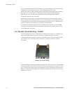
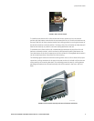
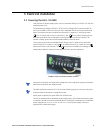
FIGURE 4: DIN-rail latch (detail)
To install the Unit with the DIN-rail brackets and latches, hold the unit in the vertical
position with the bottom out and with the top toward the DIN-rail. Position the latches over
the top of the DIN-rail, then snap the latches into holding position by moving the bottom of
the switch inwards to a vertical position. The heavy-duty DIN-rail latches and brackets will
hold the Unit securely in position, even with cabling attached to the unit.
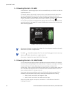
To release the Unit from the DIN-rail, simultaneously press down the top of the DIN-rail
latches to release the switch, which can then be dismounted by pulling the bottom out.
Once the bottom of the Unit is rotated out, the DIN-rail latch is not engaged and the switch
can be moved up and out, free of the DIN-rail mounting.
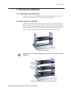
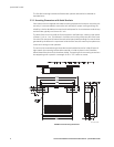
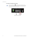
The following figure shows the vertical mounting of the Unit on a DIN-rail track for proper
convection cooling. Note there is air space in the rear, as the Unit is held out from the rear
of the panel by the mounting brackets. The Unit design uses the case for cooling (patent
pending) and needs to be mounted vertically with air flow space in the front, rear, and
sides.
FIGURE 5: Unit mounted vertically with DIN-rail brackets and latches
754709A1.CDR
754710A1.CDR