


QUICKSTART GUIDE
MULTILINK ETHERNET COMMUNICATIONS SWITCH – QUICKSTART GUIDE 11
See the Appendices of the reference manual for more details. Use an RFQ for other
variations.
3.4 UL Requirements for DC-Powered Units
1. Minimum 18 AWG cable for connection to a centralized DC power source.
2. Minimum 14 AWG cable for connection to a earthing wiring.
3. Use only with listed 10 A circuit breaker provided in building installation.
4. “Complies with FDA radiation performance standards, 21 CFR sub-chapter J”
or equivalent.
5. Fastening torque of the lugs on the terminal block: 9 inch-pound maximum.
6. For AC and HI powered units, use only with listed 20A circuit breaker provided
in building installation. Circuit breaker shall be provided in end system or
building as disconnect device.
7. Centralized DC power source cable securing; use at least four cable ties to
secure the cable to the rack at least 4 inches apart, with the first one located
within 6 inches of the terminal block.
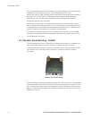
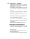
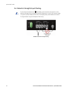
3.5 Alarm Contacts
The alarm contacts feature provides two form-A normally closed (NC) contacts to which
the user can attach two sets of status monitoring wires at the green terminal block. When
this option is present, the terminal block for alarm contacts is part of the power input panel
in the Unit case. The DC power input connection is in the same panel. A manual on-off
switch for power to the unit is not available on Unit units with the alarm contacts option, as
these two features occupy the same space in the case.
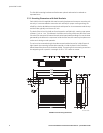
The first NC alarm contact (top position) is a “software alarm”, operated by user settings in
the Unit software. The user can disable the software alarm feature with a software
configuration command if desired. When the software alarm is enabled, the form-A
normally closed (NC) contact is held close during normal software operation. A user-
defined software malfunction, such as an SNMP trap or a software security violation,
causes the contact to open and thus trigger an alarm in the user’s monitoring system
The second (bottom position) NC alarm contact is held closed when there is power on the
main board inside of the Unit. This provides a “hardware alarm” because the NC contacts
will open when internal power is lost, either from an external power down condition or by
the failure of the Unit power supply. For an Unit with the redundant power supply option,
the hardware alarm contact will change state if any one of the power supplies fails.
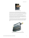
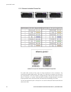
Useful information about the alarm contacts:
• The four terminal block (1, 2, 3, and 4) is adjacent to the power supply.
• The top two pins (1 and 2) are software operated.
• The bottom two pins (3 and 4) are hardware operated.
• By default, the alarm contacts are NC (normally closed).
• Software operation must be enabled to get the alarm traps. Further information is
provided in this manual.
The green alarm contacts are on the front rear area (next to the power source) of the Unit.