


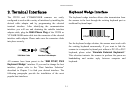
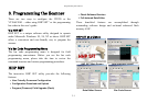

Terminal Interfaces
2-3
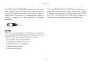
RS-232 Interface Installation
Verify the RS-232 port (COM1 or COM2) available on your
computer system.
Plug the RJ45 phone plug of the main cable into the RS-232
cable adapter.
Plug the 9-pin or 25-pin D-sub connector of the cable converter
into the desired serial port on your system.
Attach the power outlet plug of the optional AC power adapter to
the side power jack of the D-sub connector. You will hear the
power-on beep twice to signal that the scanner is ready for bar
code reading. Scan the “RS-232 Serial Interface” bar code to
configure the scanner to perform the RS-232 serial interface
operation.
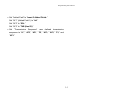
RS-232 Serial Interface
Scanning the RS-232 interface bar code above configures the
scanner’s serial parameters to 9600 Baud, 8 data bits, no parity,
and 1 stop bit, no handshaking.
Please note that the RS-232 settings of the host system must
match the scanner’s RS-232 settings.
If you are in the Windows
®
environment, you may use the “Hyper
Terminal
” to test.
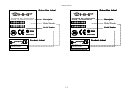
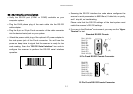
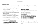
Standard RS-232 Pinouts
PIN-1: VCC
(
5V
)
PIN-2: TD
PIN-3: RD
PIN-4: NC
PIN-5: GND
PIN-6: NC
PIN-7: CTS
PIN-8: RTS
PIN-9: VCC (5V)
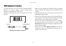
(
+
)
(
-
)
9 Pin D-sub RS-232 Female Connector
(
+
)
(
-
)
PIN-2: RD
PIN-3: TD
PIN-4: CTS
PIN-5: RTS
PIN-6: NC
PIN-7: GND
PIN-16: VCC (5V)
PIN-25: VCC (5V)
25 Pin D-sub RS-232 Female Connector