


Paper Feed Frame
1 Remove the Printer Covers.
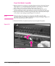
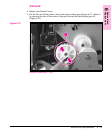
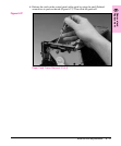
2 Remove the Pickup Roller Assembly (Figures 6-23 through 6-24).
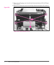
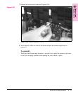
3 Disconnect the following:
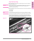
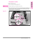
• Solenoid from the DC Controller at J204 (Figure 6-22, callout 1)
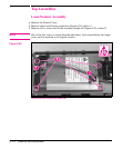
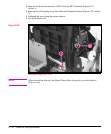
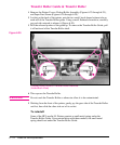
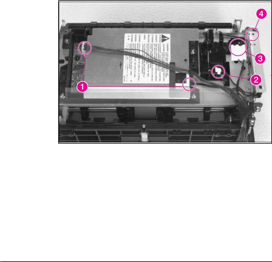
• Two connectors from the Laser/Scanner (Figure 6-26, callout 1)
• Connector from Top Cover/EP Cartridge Sensor on HP LaserJet 5L only (Figure
6-26, callout 2)
• Connector from Switch 101 (Figure 6-26, callout 3)
• Connector from Front Control Panel (Figure 6-26, callout 4)
Paper Feed Frame Removal (1 of 4)
Figure 6-26
6 - 30 Removal and Replacement