


506 Appendix B
Administration of MC/ServiceGuard
How MC/ServiceGuard Works
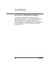
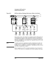
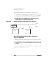
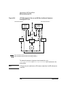
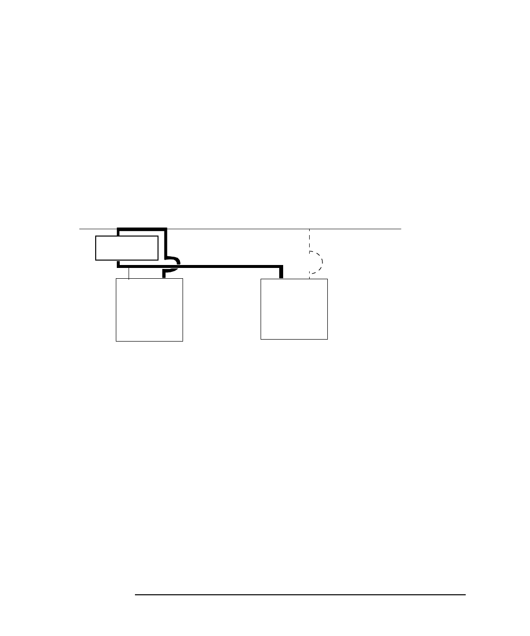
Assume that the LAN 0 network interface card on node 2 fails:
❏ The standby LAN interface, LAN 1, takes on the identity of LAN 0 on
node 2. The subnet and IP addresses are switched to the hardware
path associated with LAN 1. The switch is transparent at the TCP/IP
level.
❏ MC/ServiceGuard re-routes communications without having to
transfer the control of packages between nodes.
Figure B-4 MC/ServiceGuard LAN Switchover: After the Switch
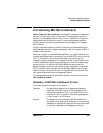
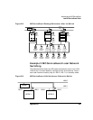
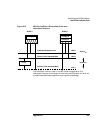
MC/ServiceGuard Redundant Data and
Control Subnets
In general, you have two redundant subnets for ServiceGuard clusters:
❏ A subnet used by the package applications for the data transfer, and
❏ A subnet used by SG to transfer the heartbeat signal to and from each
SG node.
If your network traffic is very heavy, your SG clusters should have two or
more subnets. It is common to find three LAN interfaces all bridged, with
heartbeat over LAN0, LAN1 as standby for both, and LAN3 as the data
LAN. LAN1 can backup either subnet.
Bridge
LAN 1
LAN 0
LAN 1
LAN 0
NODE 1
LAN 0
LAN 1
NODE 2