


3-4
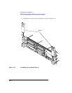
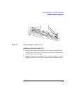
Typical Installation in a VME Card Cage
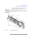
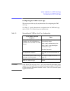
Configuring the VME Card Cage
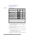
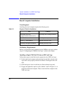
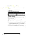
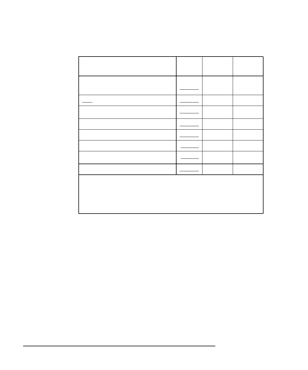
Table 3-2 Power Requirements
1 Shut down your VME application and power-off the VME card cage.
If your VME card cage backplane is autoconfiguring, see “Board Com-
puter Installation” in this chapter.
If not, refer to your VME card cage documentation for configuring its
VME backplane. Go to Step 2.
2 Ensure the backplane IACK and Bus Grant (0, 1, 2, and 3) daisy-chains
are:
• Enabled from the previous slot(s) into the slot in which the Model 743
board computer will be installed.
• Passed through all other empty backplane slots.
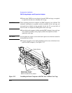
3 Set the backplane switches/jumpers to enable the board computer’s oper-
ation.
Each Model 743 Board Computer
+5V dc
Amps
+12V dc
Amps
-12V dc
Amps
If 64 MHz, current for +5V dc is 6.1A
1
If 100 MHz, current for +5V dc is 7.5A
0.1A 0.1A
RAM cards x 0.2A each =
Graphics subsystems
2
x 0.7A each =
FWD SCSI GSC card x 0.7A each =
HCRX graphics board 2.0A
PMC bridge adapter 0.6A
PMC cards on bridge adapter
3
_________ _________
Totals for Model 743 board computer
_________ _________
1. Does not include on-board graphics, if installed.
2. On-board graphics and graphics accessory cards are each separate graphics subsystems.
3. PMC cards may also draw +3.3 current that is provided through the +5 on the bridge adapter.
The +3.3 current FOR ALL PMC CARDS ON THE BRIDGE ADAPTER AND EXPANSION
ADAPTER (do not include other expansion adapter currents) must be entered into the +5 column
after multiplying the +3.3 current by .75 to convert to the actual +5 current draw.