2-2 Removal and Replacement HP OmniBook 6000
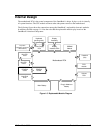
Disassembly Flowchart
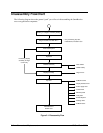
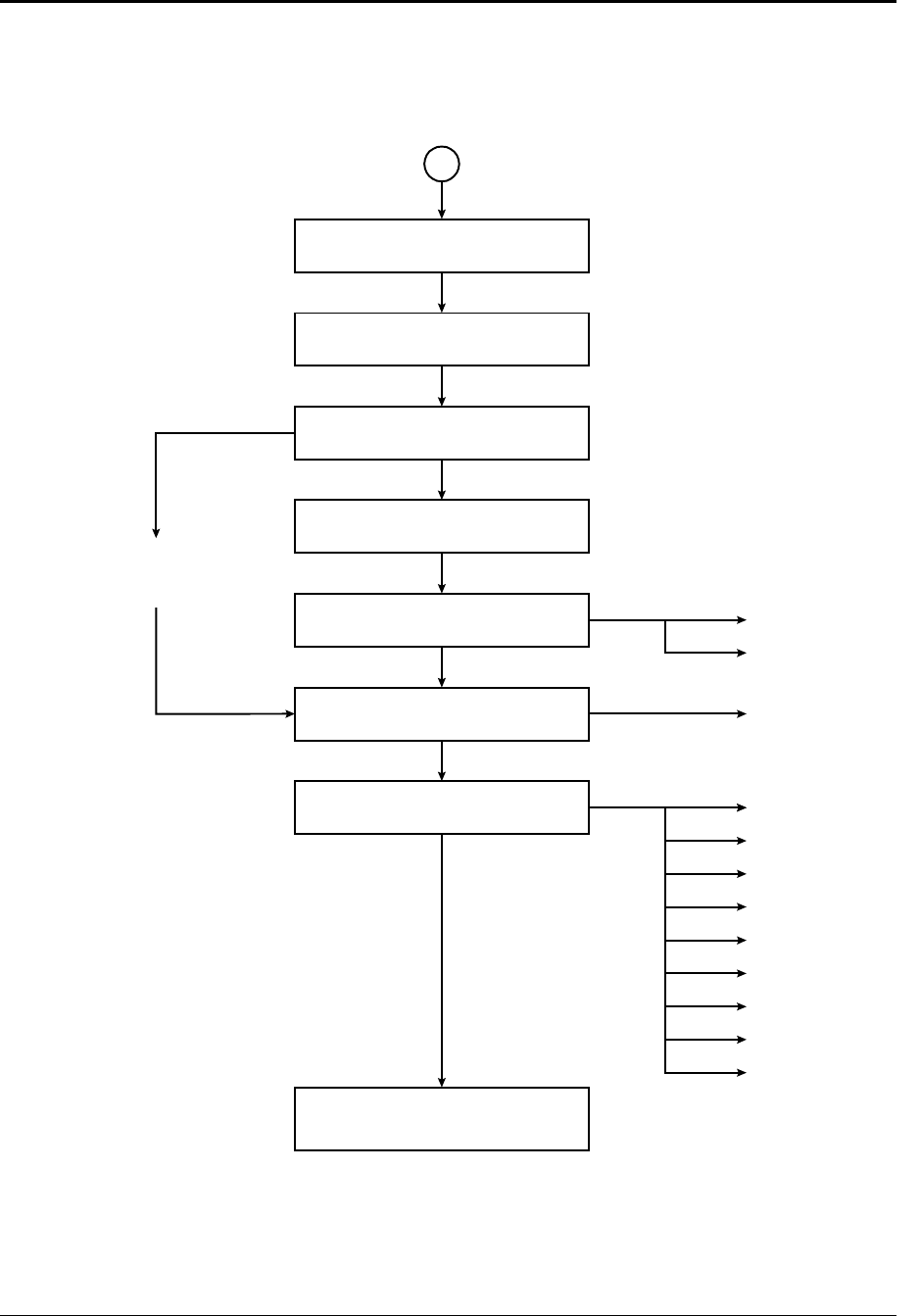
The following diagram shows the general “path” you will use in disassembling the OmniBook to
access any particular component.
Figure 2-1. Disassembly Flow
Battery, ac adapter, secondary battery
Plug-in module, hard disk drive *
* Only if removing top case,
motherboard, or bottom case.
Power button panel
Keyboard
Heatsink
(
with fan
)
Display assembly
Top case
Motherboard or
bottom case
If removing display
assembly or hinge
covers only
CPU module
CMOS batter
y
Hinge covers
PCMCIA socket
Display interface PCA
Power supply PCA
Volume PCA
Mini-PCI panel
Vent panel
Sound/IR panel
Docking doors
PCMCIA doors


