


2
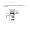
Chapter 1 Controls and Indicators
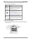
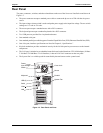
Table 1-1 provides the front panel power switch and the lower bezel LED indicator definitions.
Table 1-1. Control Panel Switch and Indicators
Additional Controls and Indicators
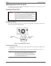
Storage devices provide additional front panel controls and indicators. The specific controls and indicators
depend on the type and model of the storage devices used. Figure 1-2 shows the controls and indicators typically
found on HP supplied devices.
Control /
Indicator Description
Power On/Off/
Sleep LED
This LED indicator provides the power state of the Server.
Steady green when the Server is operating normally.
Blinking green when the Server is in Standby mode.
Off when the Server is powered off.
Power On/Off/
Sleep Switch
The power switch turns the hp server power On or Off. If
sleep states are available, it also transitions the Server
between Power On and sleep states.
Sleep states are NOS dependent and only available if your
NOS supports power management based on the ACPI
(Advanced Configuration and Power Management Inter-
face) standard. Refer to “Applying Power to the hp server”
and “Sleep States (ACPI)” later in this chapter.
Drive Activity
LED
Flickering amber LED during any IDE or SCSI device
activity, including the CD-ROM drive(s), IDE hard disk
drives, and SCSI devices connected to the SCSI controller
board.
Off when there is no IDE or SCSI device activity.
Figure 1-2. Control Panel Indicators
FDD
FDD Activity LED
CD-ROM Drive
Disk Activity LED
Eject Button
Eject Button