


84
Chapter 7 Replacing Parts
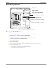
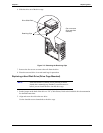
6. At the rear of the CD-ROM, carefully connect the power and data cables.
The IDE CD-ROM uses one connector on the cable from the IDE-2 connector, leaving one connector for
an optional third hard drive in shelf 4 or an optional IDE device in shelf 3.
7. Replace the upper bezel.
8. Replace the left side cover.
9. Replace the external cables and power cord.
10. Power on the server as described in Chapter 1‚ Controls and Indicators.
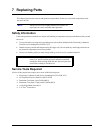
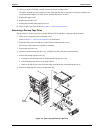
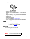
Removing a Backup Tape Drive
This procedure is used to remove the optional HP DAT 24i backup drive mounted in the third shelf.
1. If the server is operating, power down the server.
Refer to Chapter 1‚ Controls and Indicators for instructions.
2. Disconnect the power cord and any external cables connected to the server.
If necessary, label each one to expedite re-assembly.
3. Remove the left side cover.
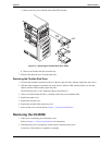
4. At the rear of the backup tape drive tray, carefully disconnect the power and data cables.
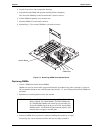
5. Remove the backup tape drive tray by:
a. Pressing in on both release tabs to release the backup tape drive tray.
b. Pull the backup tape drive tray out of the chassis.
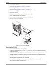
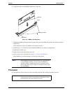
c. Remove the four screws (two from each side) securing the tray to the backup tape drive.
6. Place the backup tape drive tray in an anti-static bag.
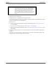
Figure 7-4. Removing the Backup Tape Drive
Extra
Screws