


HP Omnibook XT6050, XT/VT6200 Removal and Replacement 2-3
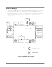
Disassembly Flowchart
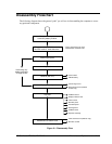
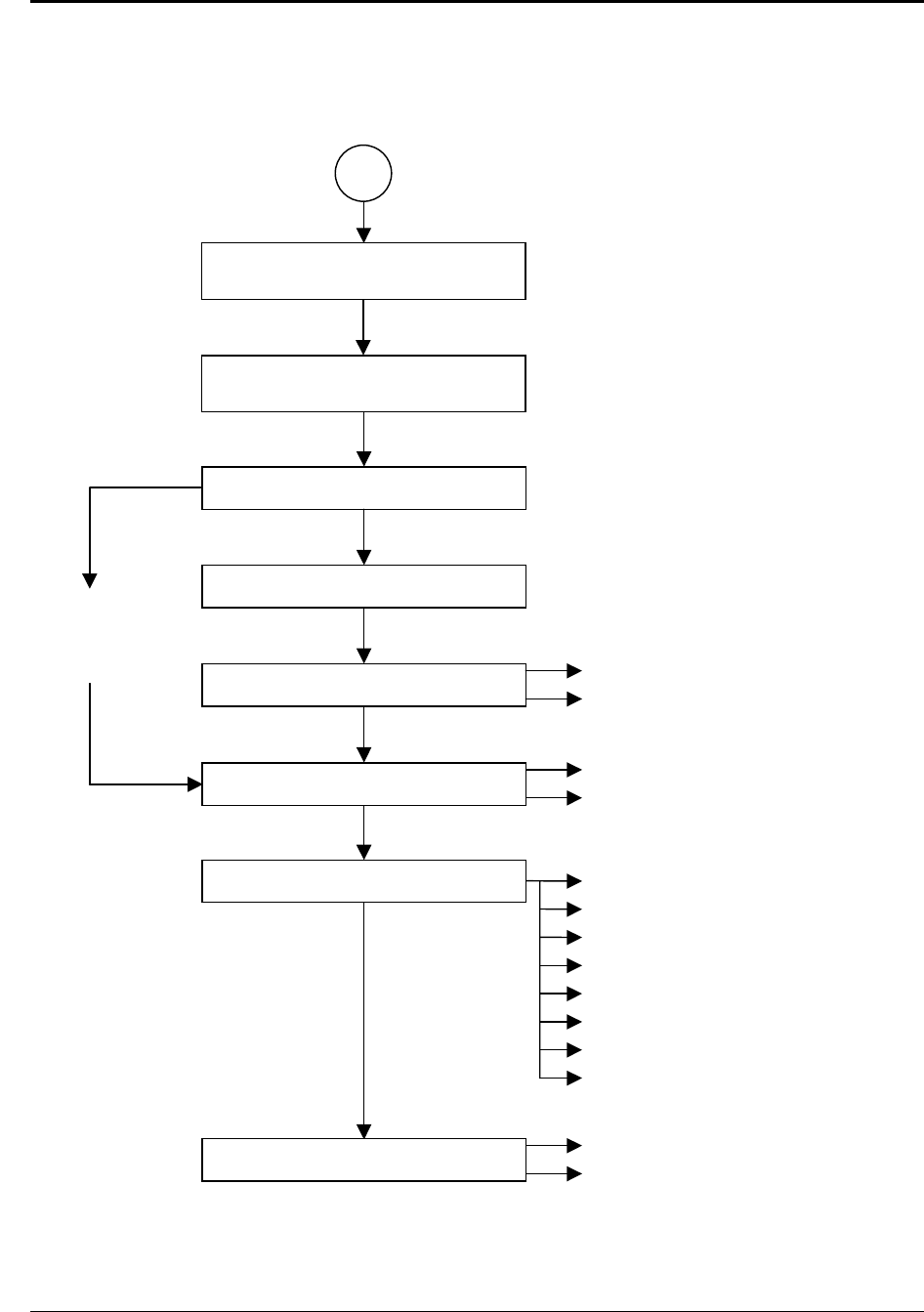
The following diagram shows the general “path” you will use in disassembling the computer to access
any particular component.
Figure 2-1. Disassembly Flow
If removing only
display assembly
or hinge covers
Display assembly
Center hinge cover
Rear antenna PCA (wireless
models only)
Top case
PCMCIA socket
Display interface PCA
Volume PCA
Mini-PCI panel
Sound/IR panel
Docking doors
PCMCIA doors
Speaker assembly
Front antenna PCA (wireless only)
Mini-PCI card #2
Motherboard or bottom case
Power button panel
Keyboard
Heatsink (with fan)
CPU module
CMOS batter
y
Plug-in module, SDRAM module,
Mini-PCI card #1, hard disk drive *
* Only if removing the top case,
motherboard, or bottom case.
Battery, AC adapter,
secondary battery module