


1 - 16
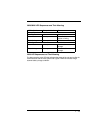
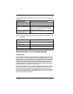
The tables below list the indication and cause of the LED illumination and beeps
for the 2020.
Note: Charging only occurs with external power applied to the 2020 or 12 volt
Host power.
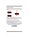
Basic Operation of the Cordless System
Cordless Base
The cordless base provides the link between the cordless image scanner and
the host system. The base contains an interface assembly and an RF commu-
nication module. The RF communication module performs the data exchange
between the cordless image scanner and the interface assembly. The control
assembly coordinates the central interface activities including: transmitting/
receiving commands and data to/from the host system, performing software
activities (parameter menuing, visual indicator support, power-on diagnostics),
and data translation required for the host system.
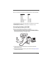
The base also is the image scanner battery charger with the external 9VDC
power source applied. Once you place the image scanner into base, the base
green LED responds according to the Charge Status Indicator table above.
The base can be powered by the Host (parasitic power mode). If the base is in
parasitic power mode without the 9VDC power source, the base will still func-
tion, but will not charge the battery.
System Condition System Status Indicator (Red LED)
Power On/System Idle LED is on
Power On/Diagnostic Error Blink LED for long duration, pulsing indefinitely
Receiving Data (2020 only) Blink LED for short duration in multiple pulses.
Occurs while transferring data to/from the RF
module or the Host port.
Base requests status from
its own Bluetooth radio
Blink LED once (occurs approx. every 30 sec-
onds)
Charge Condition Charge Status Indicator (Green LED)
Image Scanner inserted
into base
Three flashes
>80% charged On continuously
30% to 80% charged Slow flash, 1 second on, 1 second off
<30% charged Fast flash, 300 mSec on, 300 mSec off