


9 - 6
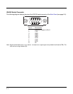
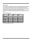
RS-232 Serial Connector
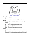
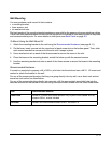
The following diagram displays the pins of the RS-232 serial connector of the Back Panel (see page 9-3):
Note: Signals referenced are for a DTE device. The base is at a right-angle to the printed circuit board (PCB). The
ninth pin has a ring indicator (RI).
Pin # Description
1 Internal Jumper to Pin 6
2 TXD
3 RXD
4 DSR
5 GND
6 DTR
7 CTS
8RTS
9RI