


6 www.honeywell.com
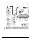
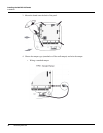
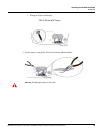
Installing the NetAXS-123 Panels
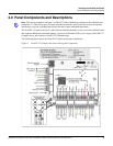
Panel Components and Descriptions
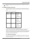
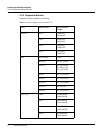
Tampers can also be supervised. They are located on the following terminal blocks:
Table 2: Supervised Tamper Terminal Blocks
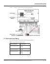
Door Status (STS) and Request to Exit (REX) for all three doors may be configured for Normally
Open or Normally Closed contacts as supervised or non-supervised. Inputs 5 (generic) and 6 (power)
are on C-TB10. All seven inputs on the Controller Board and four inputs on the Add-On Board have
default functions, but they can be configured for general purpose inputs.
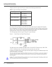
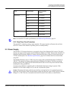
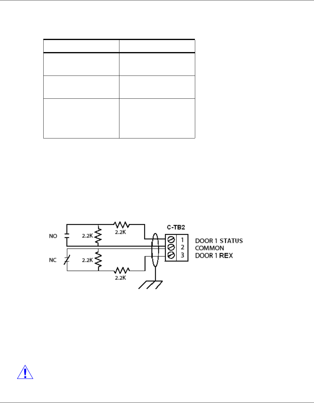
The following figure shows the typical wiring for a supervised input.
Figure 4: Typical Supervised Input Wiring Diagram
The figure above shows standard 2,200 ohm resistors. The NetAXS-123 panel accepts 1,000, 2,200,
4,700, or 10,000 ohm values. Note that both resistors must have the same value.
In addition, the Reader tampers can be supervised and capable of being used as additional inputs if the
default functionality is not needed.
The wire used for the inputs should be shielded and cannot exceed 30 ohms over the entire length of
the cable. Remember that the distance from the panel to the door must be doubled to determine the
total resistance.
Caution: The cable shield should be grounded only at the panel earth ground. Grounding at both ends
can cause ground loops which can be disruptive.
Board Configuration Terminal Block
1-Door (Controller Board) C-TB3/TMPR A
C-TB4/TMPR B
1-Door (Add-On Board) IO-TB3/TMPR A
IO-TB4/TMPR B
2-Door (Add-On Board) IO-TB3/TMPR A
IO-TB4/TMPR B
IO-TB7/TMPR A
IO-TB8/TMPR B