


40 www.honeywell.com
Installing the NetAXS-123 Panels
Installation
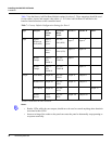
Note: The power source selected by the jumper settings shown above configure the power source for
the relay. It does not configure the power source for the panel.
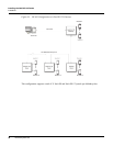
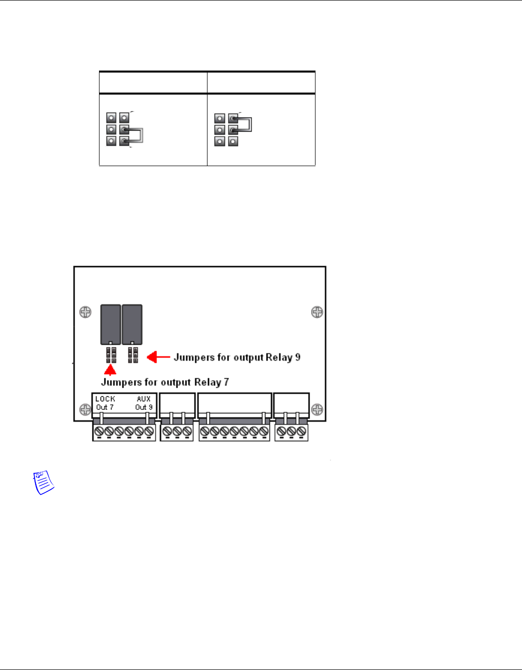
• Setting the jumpers to configure the relay contact type:
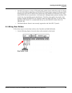
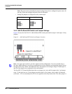
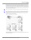
3.6.2 Add-On Board DIP Switch and Jumper Settings
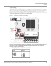
Figure 8 locates the NetAXS-123 Add-On Board DIP switch panel and the output 1 and output 3 relay
jumpers.
Figure 8: Add-On Board DIP Switch and Jumper Location
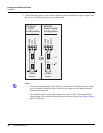
Note: The figure above shows a one-door Add-On Board configuration. If you are instead using a
two-door Add-On Board, you will see an additional two relays (and their corresponding jumper sets) to
the right of the relays shown. The additional relays and jumpers will configure output 11 and output 13,
and all of the jumpers are configured in the same manner.
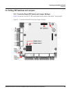
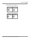
The NetAXS-123 Controller Board provides two jumper sets, one each for output relay 1 and output
relay 3. Each relay has two 3-pin jumpers associated with it. One jumper selects either self-whetted
(on-board, +12V) or external power (EXT) to be applied to the relay contact load. The other jumper is
Normally Open Normally Closed