


30 www.honeywell.com
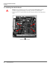
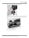
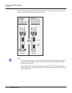
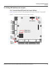
Installing the NetAXS-123 Panels
Installation
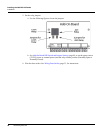
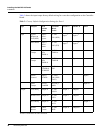
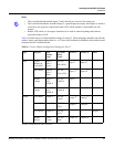
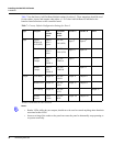
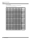
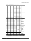
Table 5 shows the input/output factory default wiring for a one-door configuration on the Controller
Board.
Table 5: Factory Default Configuration Settings for Door 1
a
Readers A and B share the same connection.
Type Purpose Web
Default
Name
Terminal
Block
Label
Reader A Reader B Other
Input Egress/
Request to
Exit (REX)
Input 1:
Door 1
Egress
C-TB2
IN1 (REX)
Input 1
a
Input 1
a
Door Status Input 2:
Door 1
Status
C-TB2
IN2 (STS)
Input 2
a
Input 2
a
Reader
Tamper
Input 3:
Door
TMPR-A
C-TB3
TMPR A
Input 3
Reader
Tamper
Input 4:
Door
TMPR-B
C-TB4
TMPR B
Input 4
General Input 5:
GENERAL
PURPOSE
C-TB10
IN5
Input 5
Power/
General
Input 6:
POWER
C-TB10
IN6 (PWR
FAIL)
Input 6
Panel
Tamper
PANEL
TAMPER
ALTER_T
MPR
Input 20
Output Lock Relay Output #1 C-TB1
LOCK
Output 1
a
Output 1
a
Reader LED Output #2 C-TB3
LED
Output 2
a
Output 2
a
AUX Relay Output #3 C-TB1
AUX
Output 3
Reader
Buzzer
Future
Feature
C-TB3
BZR
Output 4
a
Output 4
a