


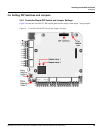

Installing the NetAXS-123 Panels
Installation
NetAXS-123 Access Control Unit Installation Guide, Document 800-05779, Revision A 31
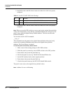
Notes
:
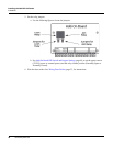
• The Controller Board includes Inputs 7 and 8 but they are reserved for system use.
• The Controller Board also includes Output 5, a general-purpose output, and Output 6, which is
reserved by the system to control the boards’ RUN LEDs and thus is unavailable for user
control.
• Reader LED, while it is an output, should never be used to control anything other than its
associated reader’s LED.
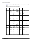
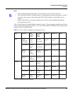
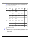
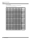
Table 6 lists the factory I/O board default settings for a door 2. These mappings should be used for the
readers, inputs, and outputs when either a 1- or 2-door Add-On Board is attached to the board-to-board
connector on the Controller Board.
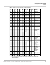
Table 6: Factory Default Configuration Settings for Door 2
a
Readers A and B share the same connection.
Type Purpose Web
Default
Name
Terminal
Block
Label
Reader A Reader B Other
Input Egress/
Request to
Exit (REX)
Input 9:
Door 2
Egress
IO-TB2
IN9 (REX)
Input 9
a
Input 9
a
Door Status Input 10:
Door 2
Status
IO-TB2
IN10 (STS)
Input 10
a
Input 10
a
Reader
Tamper
Input 11:
Door
TMPR-A
IO-TB3
TMPR A
Input 11
Reader
Tamper
Input 12:
Door
TMPR-B
IO-TB4
TMPR B
Input 12
Output Lock Relay Output #7 IO-TB1
LOCK
Output 7
a
Output 7
a
Reader LED Output #8 IO-TB3
LED
Output 8
a
Output 8
a
AUX Relay Output #9 IO-TB1
AUX
Output 9
Reader
Buzzer
Future
Feature
IO-TB3
BZR
Output 10
a
Output 10
a