


9-6
IBM Personal Computer User Guide
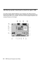
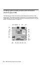
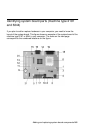
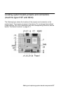
The system board, sometimes called the planar or motherboard, is the main circuit
board in the system unit. It supports a variety of devices and provides other basic
computer functions that are preinstalled or that you can install later. The system
board shown on the previous page has the following parts:
Memor
y
module sockets
(
for DIMMs
)
.
Your system board has two 168-
pin sockets for Dual lnline Memory Modules (DIMMs).The DIMM sockets
support 3.3V single-or double-sided Synchronous DRAM (SDRAM). The
maximum system memory is 1 GB.
Power Switch connector (J9)
Processor fan power connector (J3)
HDD LED and Power LED connector (J8)
Primary IDE connector (J11).
Holds signal cables that attach to IDE
channel 1.
Processor FAN, processor and heat sink (J1)
Secondary IDE connector (J12).
Holds signal cables that attach to IDE
channel 2.
Diskette drive connector (Floppy 1)
Battery (BAT1)
System battery.
Flash ROM BIOS (U9)
PCI adapter card connector (J5 - PCI SLOT1).
This is the first PCI
adapter card connector.
PCI adapter card connector (J6 - PCI SLOT2).
This is the second PCI
adapter card connector.
PCI adapter card connector (J7 - PCI SLOT3).
This is the third adapter
card connector.
USB and Local Area Network Connector (J4)
CD-ROM audio signal connector (J14)
Audio and game port connector (J13)
Power supply connecter (J21)
Keyboard and mouse connectors (KBMS1)
Parallel, Video and Serial connectors (LP1)
Digital Flat Panel connector (J10)
Front USB, headset, microphone, and volume control (J22) (for
consumer desktop model only)
1
2
3
4
5
6
7
88
9
10
11
12
13
14
15
16
17
18
19
20
21