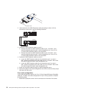
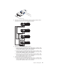
b. Locate the SMP Expansion cable that is connected to port 2 on node 3;
then, connect the opposite end of the cable to port 2 of node 6. Next, route
the cable through the node 6 cable-management arm.
c. Locate the SMP Expansion cable that is connected to port 3 on node 5;
then, connect the opposite end of the cable to port 3 of node 6. Next, route
the cable through the node 6 cable-management arm.
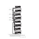
9. Connect the SMP Expansion cables to node 7:
a. Locate the SMP Expansion cable that is connected to port 1 on node 6;
then, connect the opposite end of the cable to port 1 of node 7. Next, route
the cable through the node 7 cable-management arm.
b. Locate the SMP Expansion cable that is connected to port 2 on node 2;
then, connect the opposite end of the cable to port 2 of node 7. Next, route
the cable through the node 7 cable-management arm.
c. Connect one end of an SMP Expansion cable to port 3 on node 7; then,
route the cable through the node 7 cable-management arm. Use a 2.3-m
(7.6-foot) SMP Expansion cable for this connection.
10.
Connect the SMP Expansion cables to node 8:
a. Locate the SMP Expansion cable that is connected to port 1 on node 5;
then, connect the opposite end of the cable to port 1 of node 8. Next, route
the cable through the node 8 cable-management arm.
b. Locate the SMP Expansion cable that is connected to port 2 on node 4;
then, connect the opposite end of the cable to port 2 of node 8. Next, route
the cable through the node 8 cable-management arm.
c. Locate the SMP Expansion cable that is connected to port 3 on node 7;
then, connect the opposite end of the cable to port 3 of node 8. Next, route
the cable through the node 8 cable-management arm.
11.
Route any remaining cables through the cable-management arms.
12. Secure the cables in the cable-management arms with the hook-and-loop
straps that come with the server.
Chapter 2. Installing options 55


