


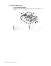
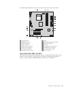
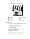
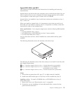
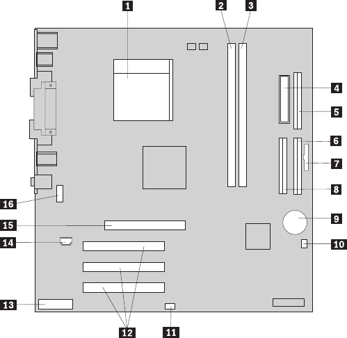
The
following
illustration
shows
the
locations
of
parts
on
the
system
board.
1
Microprocessor
9
Battery
2
DIMM
connector
1
10Clear
CMOS/Recovery
jumper
3
DIMM
connector
2
11SCSI
LED
connector
4
Power
connector
12PCI
slots
5
Diskette
drive
connector
13Front
panel
audio
connector
6
Primary
IDE
connector
14CD-ROM
audio
connector
7
Front
panel
connector
15AGP
slot
(some
models)
8
Secondary
IDE
connector
16Serial
connector
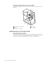
Installing
memory
Your
computer
has
two
connectors
for
installing
dual
inline
memory
modules
(DIMMs)
that
provide
up
to
a
maximum
of
2.0
GB
of
system
memory.
When
installing
DIMMs,
the
following
rules
apply:
v
Fill
each
system
memory
connector
sequentially,
starting
at
DIMM
connector
1.
v
Use
2.5
V,
184-pin,
266
MHz
double
data
rate
synchronous
dynamic
random
access
memory
(DDR
SDRAM).
v
Use
128
MB,
256
MB,
512
MB
or
1.0
GB
(when
available)
DIMMs
in
any
combination.
v
DIMMs
are
38.1
mm
(1.5
inches)
in
height.
Note:
Only
DDR
SDRAM
DIMMs
can
be
used.
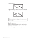
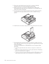
To
install
a
DIMM:
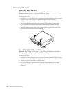
1.
Remove
the
cover.
See
“Removing
the
cover”
on
page
40.
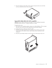
2.
To
locate
the
DIMM
connectors.
See
“Identifying
parts
on
the
system
board”
on
page
44.
Chapter
5.
Installing
Options
47