


EM78P809N
8-Bit Microcontroller
12 •
Product Specification (V1.0) 07.26.2005
(This specification is subject to change without further notice)
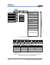
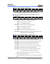
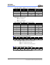
TC4D − Timer 4 Data Buffer ( Address: 0Ch )
Bit 7 Bit 6 Bit 5 Bit 4 Bit 3 Bit 2 Bit 1 Bit 0
TC4D7 TC4D6 TC4D5 TC4D4 TC4D3 TC4D2 TC4D1 TC4D0
Bit 7 ~ Bit 0 ( TC4D7 ~ TC4D0 ) : Data buffer of 8-bit Timer/Counter 4.
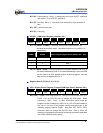
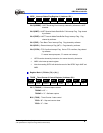
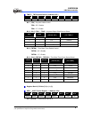
ISFR0 − Interrupt Status Flag Register 0 and INT3 Edge Detect Flag.
( Address : 0Dh )
Bit 7 Bit 6 Bit 5 Bit 4 Bit 3 Bit 2 Bit 1 Bit 0
0 0 INT3F INT3R 0 0 WDTIF EXIF0
Bit 5 ( INT3F ) : External interrupt 3 falling edge detect flag.
INT3F = “0” : Falling edge is not detected
INT3F = “1” : Falling edge is detected
Bit 4 ( INT3R ) : External interrupt 3 rising edge detect flag.
INT3R = “0” : Rising edge is not detected
INT3R = “1” : Rising edge is detected
Bit 1 ( WDTIF ) : WDT time-out flag, flag cleared by software.
Bit 0 ( EXIF0 ) : External interrupt flag (INT0). Flag cleared by software. If the
INT0EN is reset to “0”, the flag is cleared.
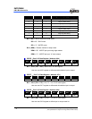
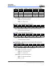
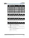
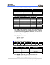
ISFR1 − Interrupt Status Flag Register 1 ( Address: 0Eh )
Bit 7 Bit 6 Bit 5 Bit 4 Bit 3 Bit 2 Bit 1 Bit 0
EXIF5 TCIF2 ADIF 0 EXIF3 TCIF4 SPIF TCIF3
Bit 7 ( EXIF5 ) : External Interrupt Flag (/INT5), flag cleared by software.
Bit 6 ( TCIF2 ) : 16-bit Timer/Counter 2 Interrupt Flag, flag cleared by software.
Bit 5 ( ADIF ) : AD conversion complete flag, flag cleared by software.
Bit 3 ( EXIF3 ) : External Interrupt Flag (/INT3), flag cleared by software.
Bit 2 ( TCIF4 ) : 8-bit Timer/Counter 4 Interrupt Flag, flag cleared by software.
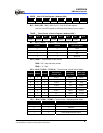
Bit 1 ( SPIF ) : SPI Mode Interrupt Flag, flag cleared by software.
Bit 0 ( TCIF3 ) : 8-bit Timer/Counter 3 interrupt flag, flag cleared by software.
"1" means interrupt request, "0" means non-interrupt
ISFR1 can be cleared by instruction, but cannot be set by instruction
IMR1 is the interrupt mask register
Note that reading ISFR1 will obtain the result of the ISFR1 "logic AND" and
IMR1.