


EM78P809N
8-Bit Microcontroller
Product Specification (V1.0) 07.26.2005
• 55
(This specification is subject to change without further notice)
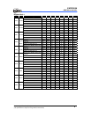
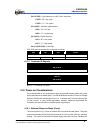
When one of the interrupts (enabled) occurs, the next instruction will be fetched from
individual address. The interrupt flag bit must be cleared by instructions before leaving
the interrupt service routine and before interrupts are enabled to avoid recursive
interrupts.
The flag (except ICIF bit) in the Interrupt Status Register (ISFR 2) is set regardless of
the status of its mask bit or the execution of ENI. The RETI instruction ends the
interrupt routine and enables the global interrupt (the execution of ENI).
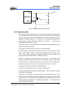
4.16 Oscillator
4.16.1 Oscillator Modes
The EM78P809N can operate in two different oscillator modes, i.e., Crystal oscillator
mode and External RC oscillator mode (ERC) oscillator mode. User can select which
mode by Code Option Register. The maximum limit for operational frequencies of the
crystal/resonator under different VDDs is listed below.
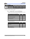
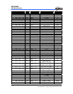
Table 10 Oscillator Modes Defined by SDCS and OSC
Mode OSC Oscillator
1 High frequency oscillator
Single Clock
0 ERC
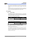
Table 11 The Summary of Maximum Operating Speeds
Condition VDD Max. Fxt. (MHz)
3.0 4.0
High frequency oscillator
5.0 10.0
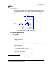
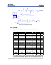
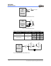
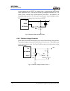
4.16.2 Crystal Oscillator/Ceramic Resonators (Crystal)
EM78P809N has a clock generator. i.e. Fc (high frequency) which can be driven by an
external clock signal through the OSCI pin.
In most applications, Pin OSCI and Pin OSCO can be connected with a crystal or
ceramic resonator to generate oscillation. Table 12 provides the recommended values
of C1 and C2. Since each resonator has its own attribute, user should refer to its
specification for appropriate values of C1 and C2. A serial resistor Rs may be
necessary for AT strip cut crystal.