


EM78P809N
8-Bit Microcontroller
Product Specification (V1.0) 07.26.2005
• 15
(This specification is subject to change without further notice)
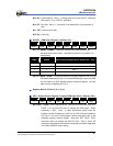
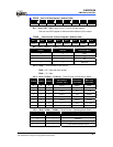
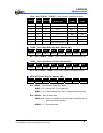
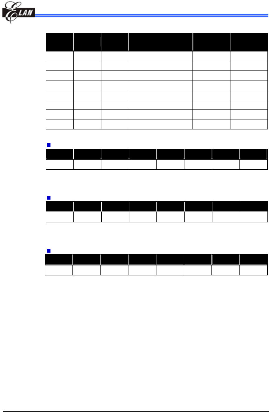
Bit 2 ~ Bit 0 ( TC2CK2 ~ TC2CK0 ) : Timer/Counter 2 Clock Source Select
TC2CK2 TC2CK1 TC2CK0
Clock Source
( Normal, Idle )
Resolution
( Fc=8M )
Max. Time
( Fc=8M )
0 0 0 Fc/2
23
1.05s 19.1h
0 0 1 Fc/2
13
1.02ms 1.1min
0 1 0 Fc/2
8
32μs 2.1s
0 1 1 Fc/2
3
1μs 65.5ms
1 0 0 Fc 125ns 7.9ms
1 0 1 - - -
1 1 0 - - -
1 1 1 External clock (TC2 pin)
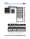
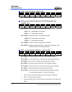
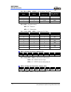
TC2DH − Timer 2 Data Buffer High Byte ( Address: 09h )
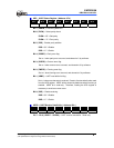
Bit 7 Bit 6 Bit 5 Bit 4 Bit 3 Bit 2 Bit 1 Bit 0
TC2D15 TC2D14 TC2D13 TC2D12 TC2D11 TC2D10 TC2D9 TC2D8
Bit 7 ~ Bit 0 ( TC2D15 ~ TC2D8 ) : 16-bit Timer/Counter 2 data buffer high byte.
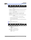
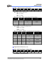
TC2DL − Timer 2 Data Buffer Low Byte ( Address: 0Ah )
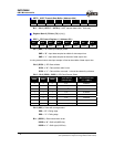
Bit 7 Bit 6 Bit 5 Bit 4 Bit 3 Bit 2 Bit 1 Bit 0
TC2D7 TC2D6 TC2D5 TC2D4 TC2D3 TC2D2 TC2D1 TC2D0
Bit 7 ~ Bit 0 ( TC2D7 ~ TC2D0 ) : 16-bit Timer/Counter 2 data buffer low byte.
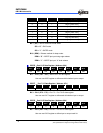
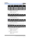
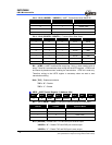
ADCR − AD Control Register ( Address: 0Bh )
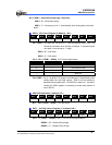
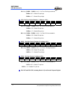
Bit 7 Bit 6 Bit 5 Bit 4 Bit 3 Bit 2 Bit 1 Bit 0
ADREF ADRUN ADCK1 ADCK0 ADP ADIS2 ADIS1 ADIS0
Bit 7 ( ADREF ) : AD reference voltage input select.
ADREF = “0” : Internal VDD, P97 is used as IO.
ADREF = “1” : External reference pin, P97 is used as reference input pin.
Bit 6 ( ADRUN ) : AD Conversion start
ADRUN = “0” : Reset on completion of the conversion by hardware, this bit
cannot be reset by software.
ADRUN = “1” : Conversion starts