


CHAPTER 7 HARDWARE SPECIFICATIONS
User's Manual U13502EJ2V0UM00
72
•
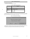
Supported ROM specifications
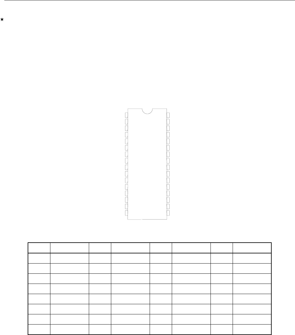
Only an EPROM with 32 or fewer pins and the pin configuration shown below can be used as the master ROM.
When the master ROM is accessed, the signature of the PROM is read to check whether the PROM is
supported. If the signature cannot be correctly read, replace the PROM with a compatible PROM of another
make.
An attempt to download a program from the master ROM socket by using a product other than a PROM and a jig
may damage the ROM socket. Never make such an attempt.
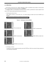
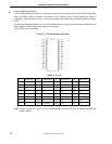
The following is pin configuration.
Figure 7-1. Pin Configuration (Top View)
V
CC
V
SS
D2
D1
D0
A0
A1
A2
A3
A4
A5
A6
A7
A12
A15
A16
A19
A18
A17
A14
A13
A8
A9
A11
_OE
A10
_CE
D7
D6
D5
D4
D3
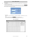
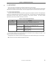
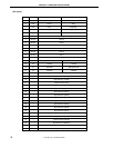
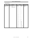
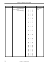
Table 7-2. Pin List
Pin Signal name Pin Signal name Pin Signal name Pin Signal name
1
A19
Note
9 A3 17D3 25A11
2 A16 10 A2 18 D4 26 A9
3 A15 11 A1 19 D5 27 A8
4 A12 12 A0 20 D6 28 A13
5 A7 13D0 21D7 29A14
6 A6 14D1 22_CE 30A17
7 A5 15D2 23A10 31
A18
Note
8A4 16V
SS
(GND) 24 _OE 32 V
CC
Note
The pin list shown in Table 7-2 is for a 1-Mbyte model. A19 and A18 of the 512-Kbyte and 256-Kbyte
models are NC.